DIY Electronic Load Built with 324 Board and Advanced Features


Assemble an electronic load using the 324 board:
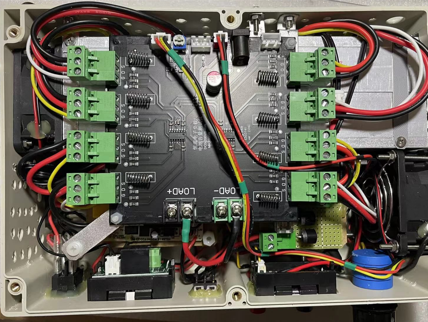
1. In order to reduce current temperature drift, replace the cement resistors on the original board with 8 Kang copper wire resistors of the same parameters.
2. Replace the potentiometer with a 3590 multi-turn one for easier attachment to the casing.
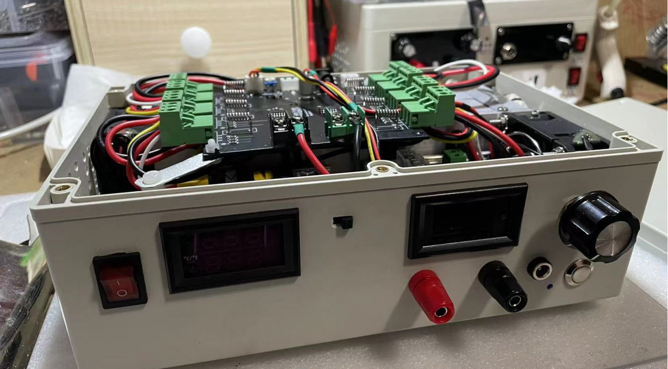
3. The 8 tubes are connected using 5.08 plug-in terminals, which makes it convenient to replace any blown tubes.
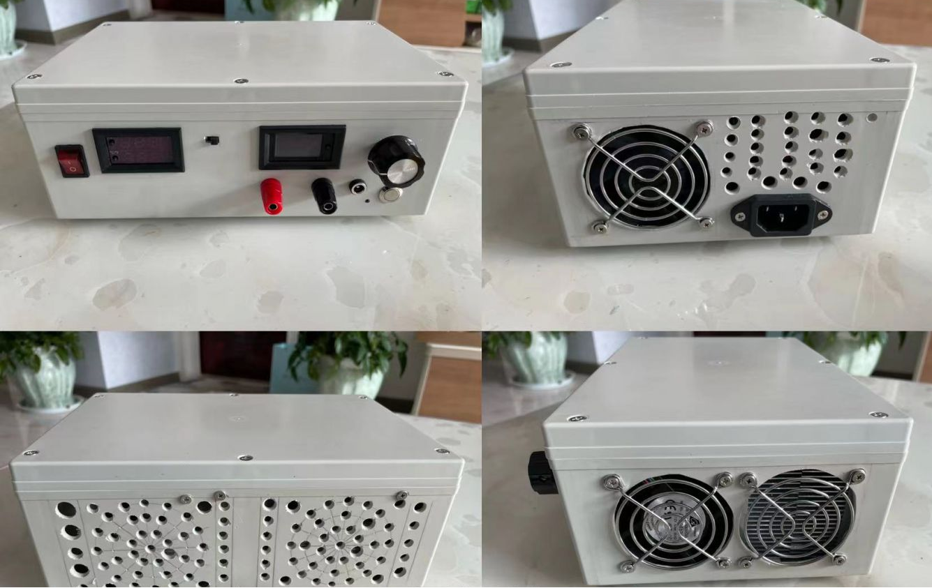
4. Dual fans are used for cooling (606025mm), powered by an independent 12V power supply with a 45-degree temperature control switch. A 3-pin, 2-gear switch is added between the fans and the power supply (a small switch between the two test leads), with one side always on and the other temperature-controlled:
① The main fan is fixed in front of the heat sink and blows air into the air duct to cool the heat sink and the tubes.
② The auxiliary fan is fixed beside the heat sink's air outlet and sucks air inward to cool the surface of the tubes and the casing.
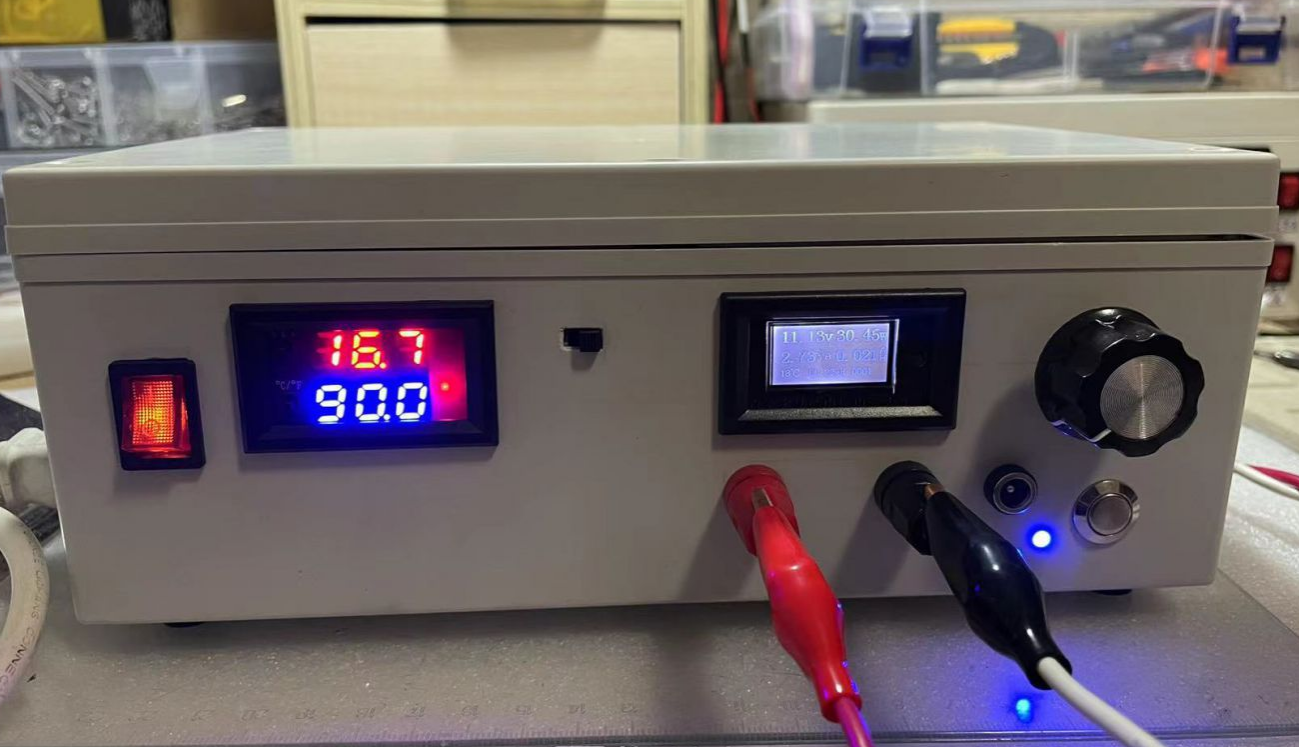
5. A temperature control module is added between the board and the 12V power supply. A temperature control probe is inserted into a hole between the farthest tube from the main fan and the heat sink (to measure the tube's true temperature), enabling over-temperature shutdown and load unloading to prevent blown tubes or boards.
6. A one-button start/stop circuit is added between the temperature control module and the board: the temperature control module is set to a 90-degree shutdown and unloading, with a 25-degree hysteresis. When the temperature drops to 65 degrees, press the one-button start/stop switch to restart the board's operation, preventing the impact of high current on the board and tubes when the over-temperature protection is triggered and re-powered.
7. The input port adopts a positive-negative pole anti-parallel diode and fuse to prevent reverse connection damage to the board.
It has been tested to be very stable, with the highest tested power being 200 watts (50V, 4A). It should be able to handle up to 400 watts without any problems.
The holes are hand-drilled. The hole above the cross-shaped socket is intentionally slanted, which turned out like that due to not controlling the depth well with the turret drill.
The casing is a bit compact, but all components fit inside perfectly.
The protruding part of the 5.08 terminal is just the height of the lid on the casing.