DIY: Creating a High-Quality Control Board


How to Create a High-Quality Control Board?
Yesterday's DIY post covered the basics, but now we'll dive into the finer details of control board creation, with some adjustments to the design.
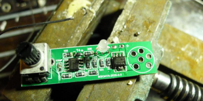
We removed two resistors from the original design, modified the LED hole spacing, and maintained the use of the 6-pin aviation plug. We also included three sleep modes:
1. Vertical sleep for the joystick (for mid-task breaks)
2. 3-minute automatic sleep (for when you forget to turn it off)
3. Sleep mode for the soldering iron stand
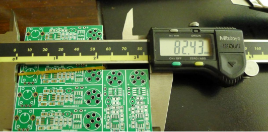
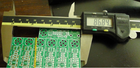
This board size is suitable for connectors.
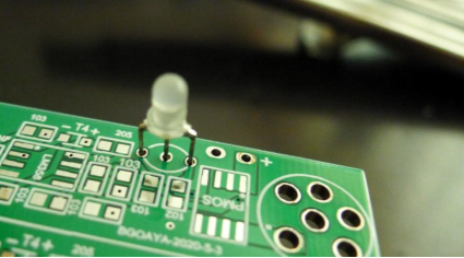
And it is also abandoned the default LED package to make it easier to insert.
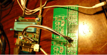
Programming the microcontroller is still the same as last time, using the trickster board to burn the program.
When soldering, be careful to avoid errors, such as soldering a resistor instead of a capacitor due to a mislabeled circuit board.
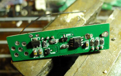
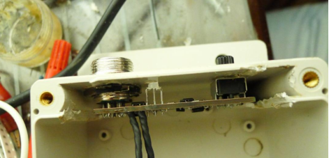
The backside
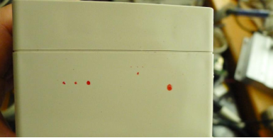
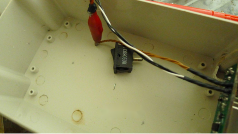
Find a box
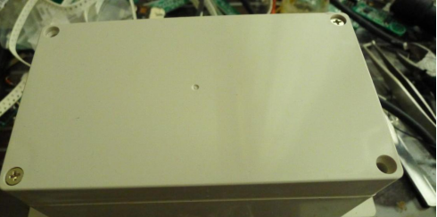
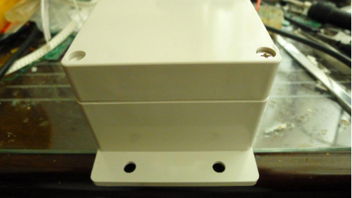
Drill holes
After installation, the board can be tested.
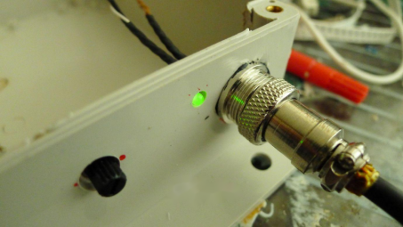
And if everything is working correctly, a knob cap can be added.
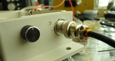
If you don't have a suitable transformer, you can wait until you have one. While many prefer switch-mode power supplies, a transformer is still a reliable option.
Testing the sleep modes, including the vertical sleep for the joystick, will ensure that the control board is working properly. Once completed, you will have another backup control board to add to your DIY collection!


