DIY Spot Welder Guide: Capacitor-Based Build & Upgrades


Discover the step-by-step journey of building your own spot welder, split into three parts for continuous upgrades! In the industry, opinions are divided between capacitor-based and transformer-based spot welders. Considering infrequent usage and the complexities of modifying transformer-based welders, starting with a capacitor-based welder is a viable option. Hardware-wise, opt for optocoupler detection for electrode input and employ the TLP250 high-speed optocoupler driver for output.
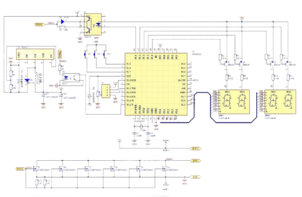
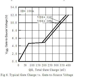
For the MOSFET, select AUIRFS8409 with low internal resistance and high current suitability for spot welding. Since AUIRFS8409 saturates at a maximum current of 200A under 5V drive voltage, increasing the ID current necessitates raising VGS. Thus, adding a boost circuit is necessary to achieve a maximum current of 400A when VGS is 12V.
Use the XL6012E1 boost chip and employ the Toshiba TLP520 optocoupler for driving. The input voltage range for TLP520 is 10-35V, with a switching speed of 0.5us. The circuit employs a three-level menu system with a 4-digit LED display, reflecting the PCB design. Due to the higher current involved in spot welding, allocate a 10mm space for installing copper bars both above and below. The hole spacing is 23mm, with the rightmost hole at 29mm. The diameter of the holes on the left side is 5mm, while those on the right side are 8mm.
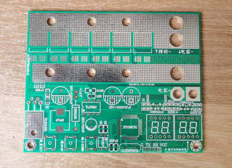
For a less complex option, the STC89C52 QFP44 package can be used. Begin by testing the program with jumper wires.
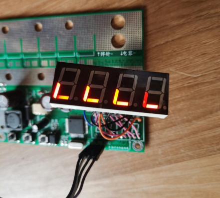
Upon startup, rotate all four LED displays five times simultaneously. There seems to be a slight issue with the camera angle.
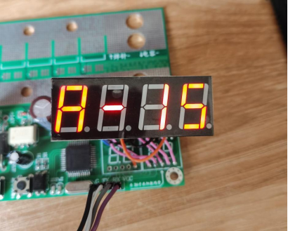
Menu A allows for setting the positive pulse width for spot welding, ranging from 0.1ms to 9.9ms, with a default of 1.5ms.
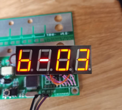
Menu B displays the pulse interval, adjustable from 0.1ms to 9.9ms, with a default of 300μs.
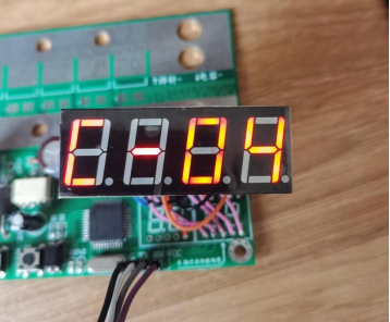
Menu C shows the number of pulses per spot welding, with a range of 1-20 pulses and a default of 4 pulses.
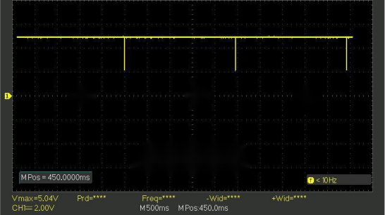
To facilitate observation during the debugging process, set the spot welding pulse interval to 2.5 seconds. In the complete version of the program, spot welding occurs once every 2.5 seconds, after which it no longer triggers.
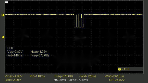
For a four-pulse sequence, the pulse time is 1.2ms, and the interval is 240μs. Note that the delay-based calculations may not be entirely accurate.
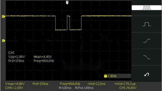
Explore the possibilities of dual-pulse output.
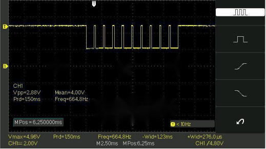
For a sequence of ten pulses, the pulse time is 1.2ms, and the interval is 270μs.
Default pulse settings. From the waveform perspective, there don't seem to be any significant issues. Now, it's time to wait for the capacitor MOS to be in place before proceeding with spot welding.


