DIY Spot Welder Upgrade: Enhanced Performance


The program from the previous issue can be further optimized for better usability, allowing for the creation of a compact and powerful spot welder using existing materials at hand.
In terms of hardware, there are several differences compared to the previous version:
1. The microcontroller unit (MCU) has been changed from STC89C51 to STC15W408AS. This 1T MCU offers a faster processing speed and a wider voltage range of 2.8V to 5.5V, addressing the shutdown issue related to weak capacitors.
2. The EC11 encoder is now used for the buttons, providing more flexible functionality and avoiding hand cramps when adjusting parameters over a wide range.
3. The boost circuit has been updated from XL6012 to MT3608, effectively reducing the Bill of Materials (BOM) cost as the boost module costs only around one or two yuan.
4. The MOSFET has been changed from AUIRFS8409 to 4N04r8 to save costs by utilizing available components.
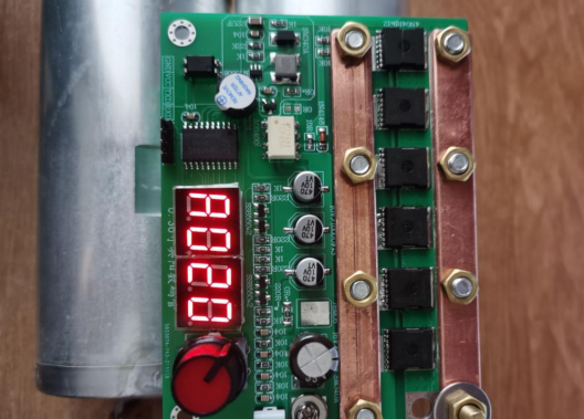
5. The device is compatible with a wide range of power supply voltages from 5V to 12V. With a 5V power supply, only the components inside the white circle and the two 0-ohm resistors marked with an asterisk need to be soldered. With a 12V power supply, the components inside the white circle can be omitted, and only the 0-ohm resistors and 7805 need to be soldered.
In terms of functionality, there are several differences compared to the previous version:
1. The previous three-level menu with two-digit display has been upgraded to a four-level menu with three-digit display. The menu options are as follows: A for welding time (0-25.5ms), B for pulse interval (0.1-15ms), C for the number of pulses (1-4 pulses), and D for welding delay detection (0.5s-5s).
2. A buzzer has been added to provide audible prompts during parameter adjustment or welding processes.
3. A 5-minute automatic shutdown feature has been added when there is no user activity. Welding or parameter adjustments will reset the timer.
4. The device includes a short-term parameter storage function. After an automatic or manual shutdown, the parameters can be saved for over half an hour when the power is disconnected (the capacitors with designed capacity on the board should be able to store the parameters for over an hour).
5. The encoder now operates as follows: rotating left decreases the parameter value, rotating right increases it. Short pressing switches the menu, long pressing for over 2 seconds shuts down the device, with three beeps from the buzzer as a prompt.
6. For protection, when the device is in shutdown state, rotating the encoder will activate the display and allow parameter adjustments, but no welding pulses will be output. Pressing the encoder button is necessary to power on the device for welding. This is not a bug but a measure to prevent accidental damage to the board.
Note: Please be aware that capacitor quality varies. Do not challenge the limits of the device at the expense of personal safety.
Schematic Diagram
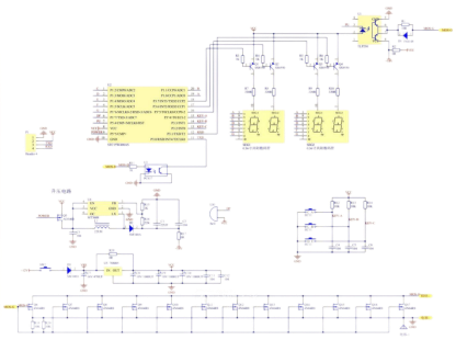
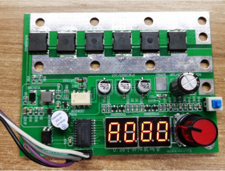
The PCB design is double-sided, with six MOSFETs on each side. The display remains the same as the previous version, utilizing a 4-digit LED display, with the addition of a buzzer.
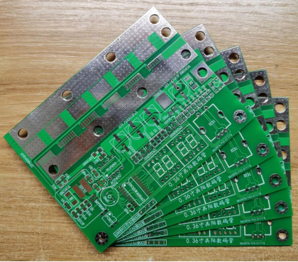
Gather the necessary components and start soldering.

The boost circuit uses a pre-made module, which can be directly installed on the board.

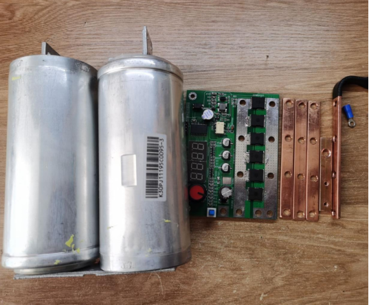
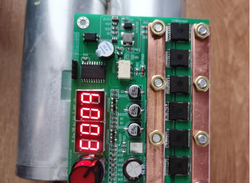
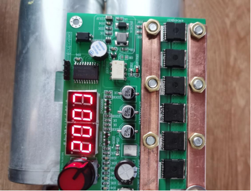
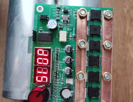
The completed board after the soldering process.
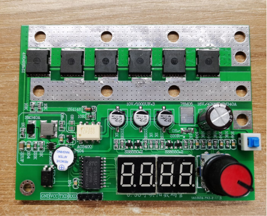
If you only have a 470μF capacitor, it can also be used. The back of the board also has six MOSFETs.
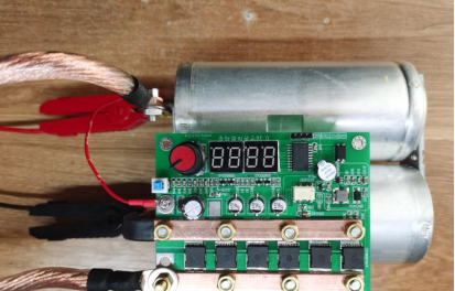
The programming process can be quite tedious. It's similar to the previous version, where upon startup, all four digits on the display rotate six times. The default display shows "A080," indicating the A menu with a welding time of 8.0ms. Due to limited IO ports on the microcontroller, the decimal point was reassigned to the buzzer.
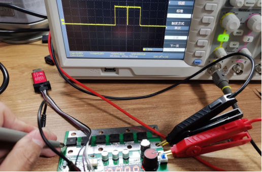
Testing with double pulses:
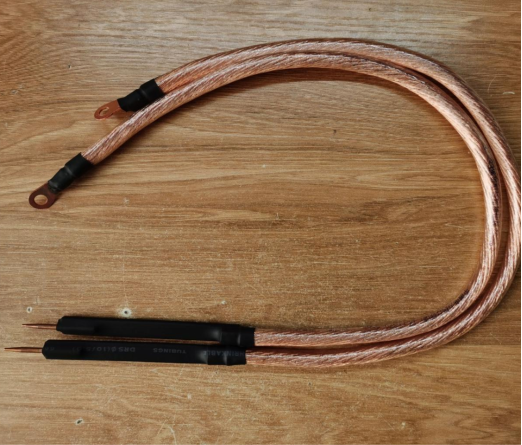
Purchased a meter of 25-square multi-strand soft copper wire.
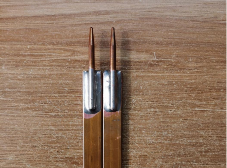
Cut a piece of 3x10mm copper bar (leftover from the previous spot welder project, already oxidized). Also, split the welding needle in half from the middle, using inexpensive ones.
Measured and marked the desired length, drew lines, and soldered them together.
Applied the same process to the other end: wrapped it with copper tape to prevent the wire from spreading out, then soldered it.
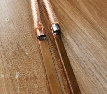
Covered with heat shrink tubing, and a pair of spot welding pens were ready.
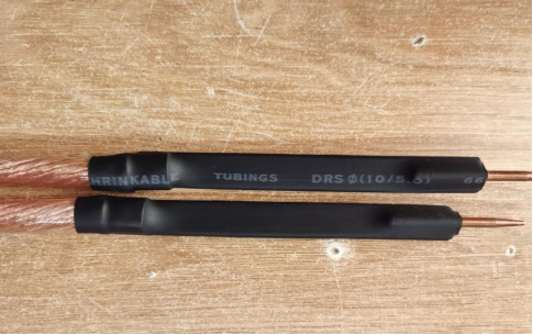
Overall, it looks quite good.
Two types of copper bars were used on the board: one with dimensions of 3x10mm for connections and the other with dimensions of 2x10mm for current collection.

The capacitors are relatively inexpensive, but they have a tendency for self-discharge, and their internal resistance is unknown.
The assembly process is omitted; simply follow the markings on the board.
Due to varying capacitor quality, the default parameter has been changed from 8ms to 2ms.
The pulse interval is set to 300μs.
There are two pulses.
The welding delay is set to 1.5s.
Let's try it out: start by spot welding a 0.15mm nickel-plated steel strip, stacking it to a thickness of 0.3mm.
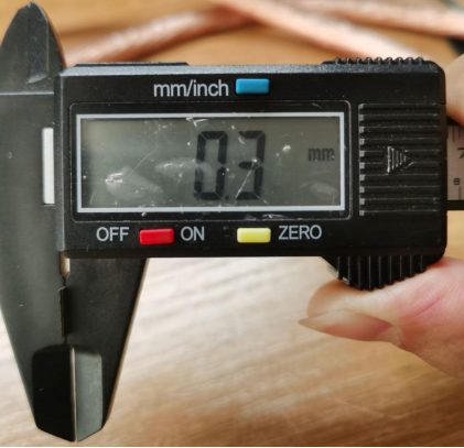
Set the welding time to 3ms, and the resulting weld spot is quite impressive.
Next, spot weld a 0.2mm pure nickel strip, stacking two pieces to a thickness of 0.4mm.
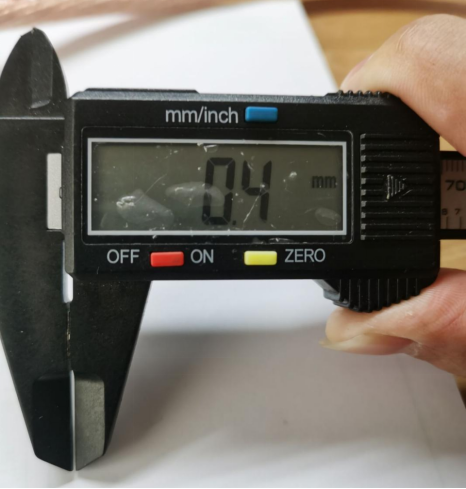
The welding time is set to 15ms because there is only one pair of capacitors with high internal resistance. If the time is too short, the weld won't hold, and if it's too long, the weld spot will turn black due to excessive heat.
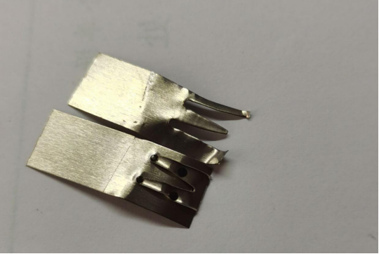
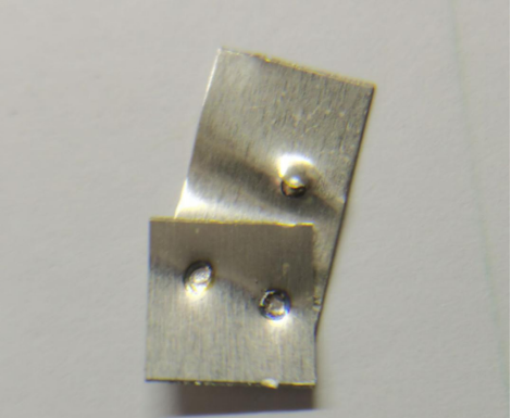
One weld penetrates through while the other doesn't. That's the characteristic of a unipolar spot welding machine.

The result of spot welding the 0.15mm nickel-plated steel strip and the 0.2mm pure nickel strip is just satisfactory.
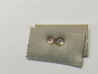
0.15 nickel plating and 0.2 red copper strip butt welding.
Copper is soft and won't tear as much as nickel plating.

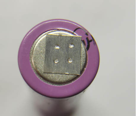
Finally, let's spot weld a battery using 0.15mm nickel-plated steel, with a welding time of 3ms. The weld spot looks remarkably flawless.