DIY Supercapacitor Spot Welding Machine


How to make a supercapacitor spot welding machine?
Continuing from the previous issue, using the same circuit and microcontroller program. An additional charging circuit has been added, which can also reduce the installation of several components to provide power to the microcontroller circuit when welding lead-acid batteries.
Charging circuit related instructions:
1. When using a 12V lead-acid battery instead of a supercapacitor, for the positive side: directly short-circuit the positive terminal with the point marked in the frame next to the positive electrode. On the back side, do not install the following components: D3, D6, Q1, Q2, R2, R3, R5, DC1, a total of 7 components.
2. Regarding the charging current, the BOM table provides a resistor R28 with a value of 0.5 ohms, resulting in a current slightly above 1A. You can decrease the resistor value to increase the current, such as 0.25 ohms for slightly above 2A, or around 0.15 ohms for about 4A (rough calculation). The maximum charging current can reach 5A. Calculate and choose the appropriate values based on the power supply capacity you have for charging.
3. Regarding the charging voltage, since there is no charging balance design, the charging voltage is set to 5V. The formula to calculate the output voltage is: V = 1.25 * (1 + R1 / R4).
Attention and frequently asked questions regarding circuit board soldering:
1. The fundamental principle of the spot welding machine is to control the pulse width, pulse interval, and pulse count of the spot welding.
2. Due to the thin pins of the microcontroller, they are prone to solder bridging and contamination from other impurities. It is recommended to solder them last, and if possible, clean them with board cleaning solution. Many reported issues with the program are usually related to this problem.
3. The spot welding machine can support high-current batteries ranging from 12V to 48V as a power source.
Spot welding machine button functions: There are two buttons with the following functions:
1. Button +: Default page: Short press to enter the menu selection page; long press to clear the spot welding count to zero. Menu page: Short press to cycle through the menu options in order; long press to return to the previous menu. Parameter configuration page: Short press to increment the parameter value.
2. Button -: Default page: Short press to toggle between voltage and spot welding count display. Menu page: Short press to confirm menu selection. Parameter configuration page: Short press to decrement the parameter value; after adjusting the parameters, long press to return to the menu selection page.
Automatic mode functions [A].[d].[E].[F].[U].[H]
[A] Spot welding level 1-30.
[d] Spot welding pen trigger delay time, range: 0.5s to 3s.
[E] Buzzer output settings: output during spot welding, output during button press, simultaneous output, or no sound (four modes).
[F] Automatic shutdown delay setting: adjustable range of 1-30 minutes; 00 for no shutdown.
[U] After modifying parameters, automatically return to the following settings: 1. Automatically display voltage, 2. Automatically display spot welding count, 3. Automatically turn off the digital display, 4. No automatic return.
[H] Switch between automatic mode and manual mode, and restore default parameters: input "33" with the two buttons to switch between automatic and manual modes, input "66" to erase all set.
When in manual mode, the display shows [A]..[C][d].[E].[F].[U].[H]
[A] sets the pulse width parameter, ranging from 1 to 99 milliseconds. The pulse interval parameter can be set between 0.1 and 9.9 milliseconds.
[C] sets the pulse count parameter, ranging from 1 to 99 counts. The rest of the settings are the same as in automatic mode.
In the case of automatic shutdown, either of the two buttons can wake up the system.
When downloading the program, please select 12MHz, as timing will not be accurate and the program may not run properly otherwise.
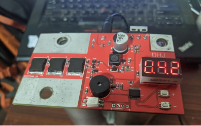
Image of the actual device.
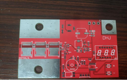
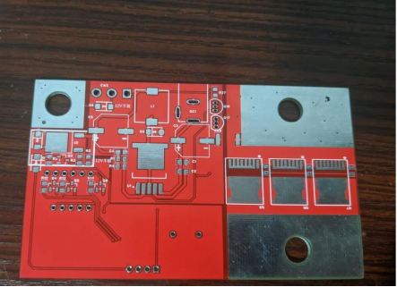
Image of the finished product.