DIY Radio: RDA5807FP & STM32F030F4P6 Upgrade


Unlock the world of microcontrollers with this captivating article on building an RDA5807FP radio. From disassembling to upgrading with an STM32F030F4P6 microcontroller, discover how to control the amplifier, add features like indicator lights and presetting stations, and optimize power consumption. Get ready to embark on a radio-building adventure!
If you are interested in microcontrollers, you can take a look at this article to make an RDA5807FP radio.
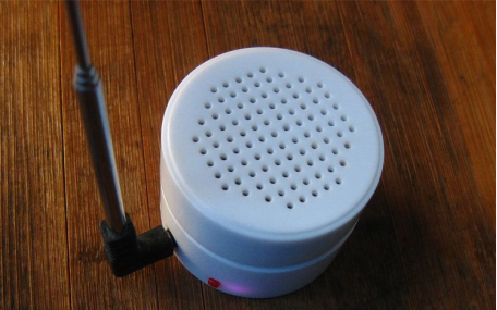
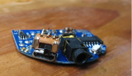
Plug the antenna into the headphone jack. The red one is the power switch, and above the charging port is the amplifier switch.
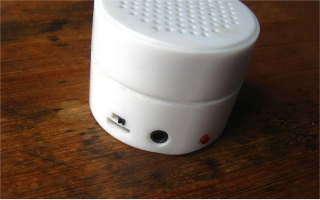
On the other side, in the middle, is the battery level display, with channel+/- and volume+/- buttons on either side.
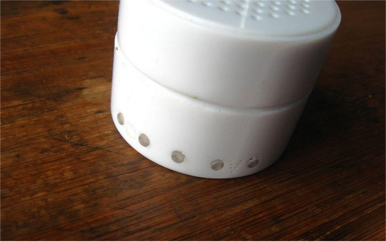
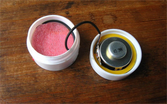
It is made using a small box similar to those used for creams, like many cosmetic boxes. There is a shallow layer on top.

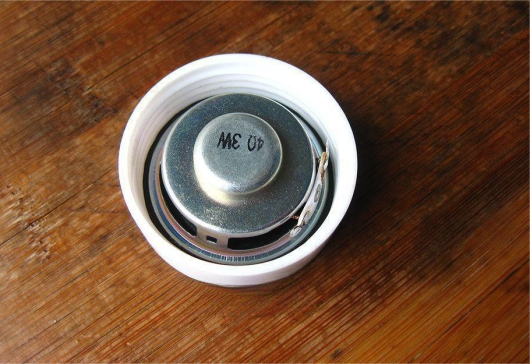
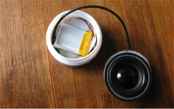
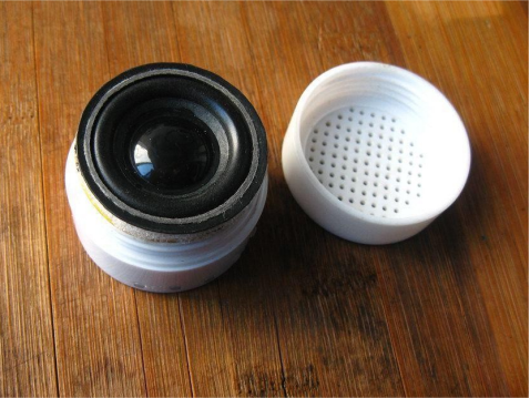
If you cut a circle from the edge and remove the shallow layer, you will find a large space inside that can be utilized. The lid of this box perfectly fits a small 4cm speaker. This type of speaker has good sound quality, so you can create a radio with it.
Before upgrading, let's start by disassembling it.
The battery is 500mA, but it can actually be larger. Make a hole in the lid.
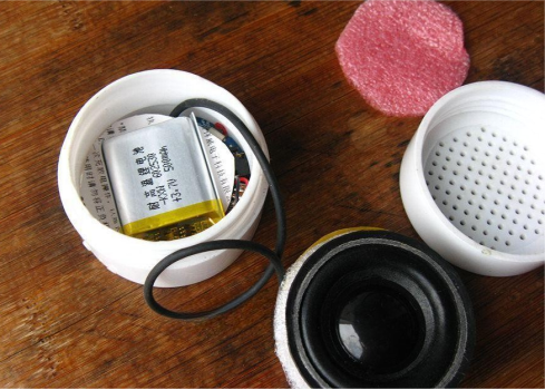
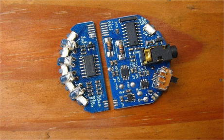
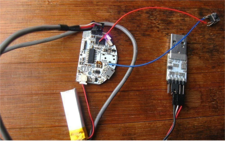
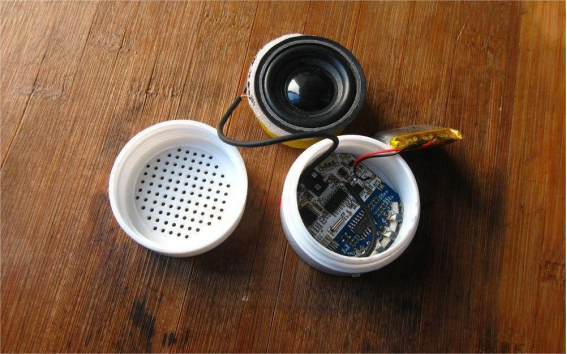
Take out the battery and the compartment to reveal the circuit board.
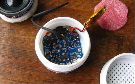
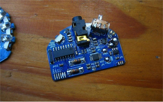
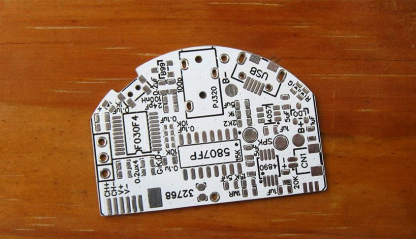
On the other side, there are buttons and the circuit for measuring electricity. Two boards are connected.
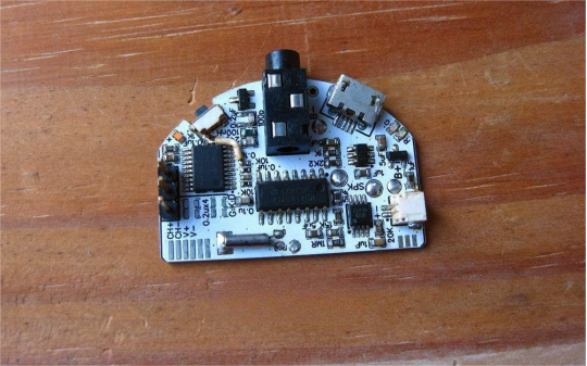
Remove the boards. The main board has the 5807FP+4890 amplifier+LDO+4057 charging components, while the small board has an LM324 battery voltage measurement circuit and a few switches.
For this circuit, the pin layout is the same as the FP version of the 5807 and GS1299. When pin 6 is pulled high, no microcontroller is needed as it has five built-in switches.
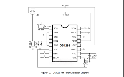
However, this means there will be no power indicator, and the amplifier cannot be controlled.
To control the amplifier, a separate toggle switch needs to be installed. This switch is a three-pin switch soldered on the USB port with the pins facing up. One drawback is that the amplifier needs to be manually turned off after each use.
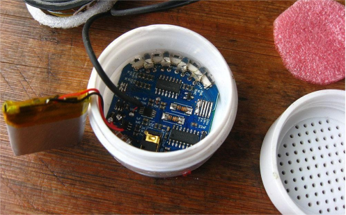
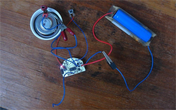
Let's begin the upgrade by cutting and grinding the board.
If you don't want to go through the trouble, the small board can remain unchanged and still be used.
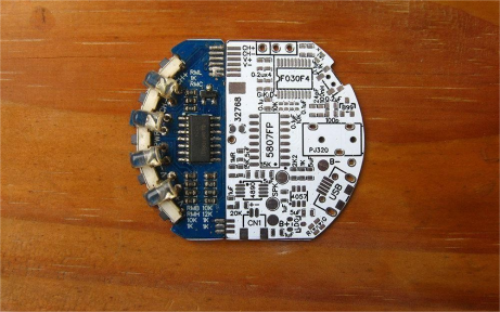
By using an STM32F030F4P6 microcontroller, the amplifier can be controlled together. Additionally, an indicator light is added to show the status, and other features such as presetting radio stations and timed shutdown can be included.
So, this circuit is required. Pull pin 6 low to ground, and pins 7/8 become I2C communication pins.

Replace the amplifier with AD4150.
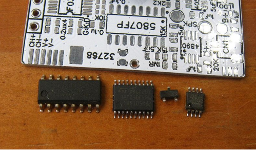
Solder the components in place, leaving the amplifier for testing later.
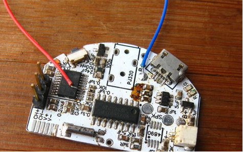
Turn on the microcontroller, and it should be working properly.
The program is simple. Delete the screen part, change the port numbers, and add amplifier control. Then test the amplifier.
Test the power consumption. Lower volume settings save power.
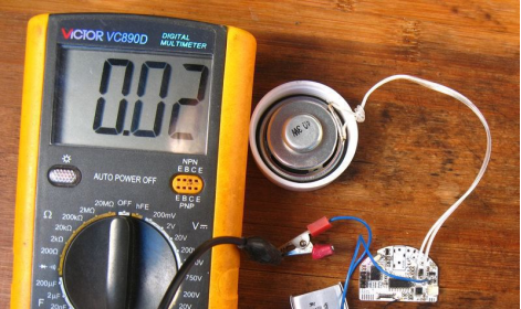
Higher volume settings consume more power.

Press the power button to enter Standby mode, with a power consumption of 25uA.

After finishing the program test, solder all remaining components.
Prepare for final assembly. Insert the buttons, which are made from a few discarded LEDs. Fit both boards together and solder the connecting points. Then solder the speaker and the battery.
Place two foam pieces next to the battery to prevent it from moving around.
Add the compartment layer and insert the speaker.
Screw on the lid, and assembly is complete. You can now listen to music by turning on the switch.


