
This text is a modification guide for a power supply. To avoid damaging the original casing, an externally mounted method is used to connect the voltmeter and ammeter, which can be adjusted from 0-55V and 0-60A.
The power supply model is as follows: Emerson R48-2900U Snowflake Iron Shell Dual Board.
Disassemble the power supply completely.
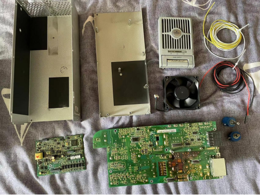
Pay attention to comparing the control board models.
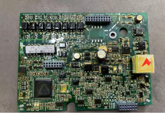
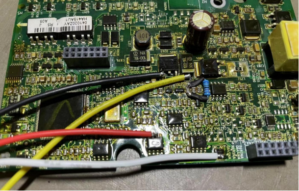
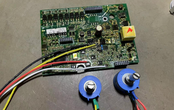
Remove the resistor at position R653 with the marking "562". Parallel a 68K resistor on resistor R650 (the higher the parallel resistor value, the higher the output voltage). Scrape off the solder mask at the following four pad positions: the left pin of U805, C834 near one side of R650, pins 2 and 3 of U709, and the pin of D601 near the edge of the control board.
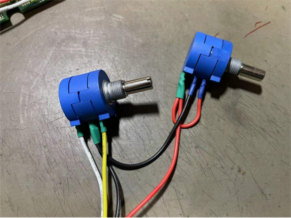
Prepare one 100K potentiometer (for voltage adjustment) and one 500-ohm potentiometer (for current adjustment). Find four thin wires of different colors and connect them as follows: black wire connects to the first pin of both potentiometers, red wire connects to pins 2 and 3 of the 500-ohm potentiometer, white wire connects to the second pin of the 100K potentiometer, and yellow wire connects to the third pin of the 100K potentiometer.
Solder the four wires of different colors to the four scraped pad positions as shown in the diagram.
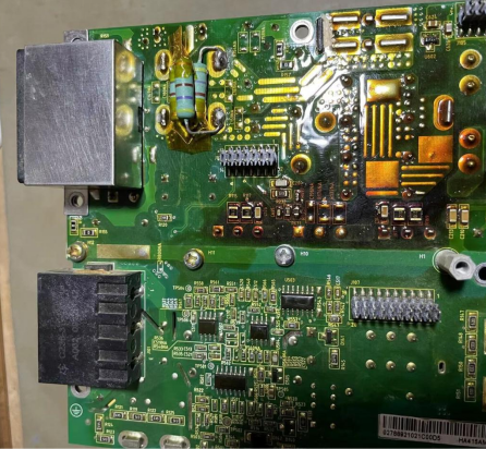
Parallel a resistor of around 1.5K, with a power rating of 5W or above, at the positive and negative terminals of the power board near the output port to create a dummy load. This resistor can be omitted if desired. With this resistor, when reducing the voltage from high to low, the pressure release is faster, and the displayed voltage drops quickly; conversely, it is slower.
Install the control board back onto the power board, connect the multimeter, and turn both potentiometers counterclockwise to the minimum position. Power it on and test. The multimeter should show 0.00 or a few volts, which indicates normal operation. If at this point, when turning the voltage adjustment potentiometer clockwise, the voltage does not change, simply turn the current adjustment potentiometer clockwise one full turn first, and then the voltage adjustment will work correctly. This is because if the current is limited to 0, there won't be any voltage.
Next, create an externally mounted voltmeter and ammeter. You'll need a 100V/100A meter head, a 100A shunt, a boost module, an old mobile phone battery, a DIP switch, a DC socket, 1 meter each of red and black #10 silicone wire, several high-current copper terminals, and a mobile phone case. The meter head is powered by the boost module, and the DC socket is connected to the positive and negative terminals of the mobile phone battery for external charging. Refer to the diagram for details.
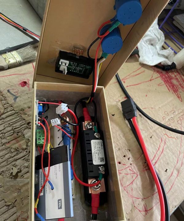
Install the two potentiometers into the voltmeter case and test it again after powering it on. Everything should work fine.
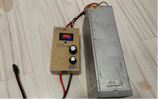
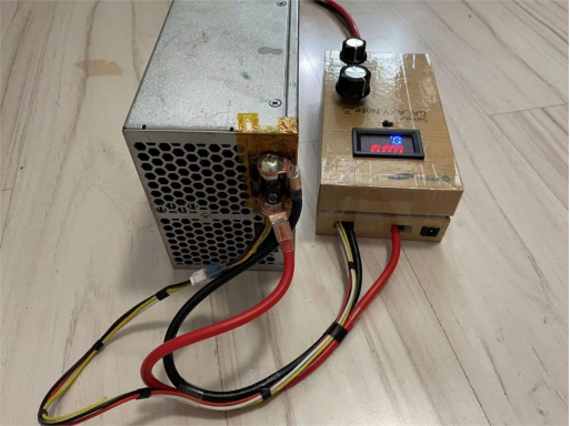
This external voltmeter setup can be quite cumbersome. Instead, you can power the voltmeter directly from point L252 on the control board and create an opening at the rear of the power supply casing to mount the meter head and potentiometers. If you're currently using this power supply without the adjustable feature specifically for supplying power to ZVS, then the external setup is convenient for monitoring the current situation.


