
If you're looking for a compact, high-capacity, high-performance, and stylish power bank, then you might want to check out the content of this article.
Online, there's a perfume power bank that uses the 18650 battery and has the smallest size. However, its capacity and performance are lacking, with most having capacities below 3000mAh and maximum output currents of only 1.5A (with some being 1A). There are almost no 18650 perfume power banks with 2A output (single cell), though 21700 ones exist with 2A output, and some even support fast charging. But since the priority is to keep it small, the 21700 option is not the first consideration. Therefore, the only option is to custom-make one.
Everything else is relatively easy to handle, but the casing is a challenging part to process. Online, there are many perfume bottle-shaped cases available. If you find them too big or not visually appealing, you can choose the one shown in the pictures.
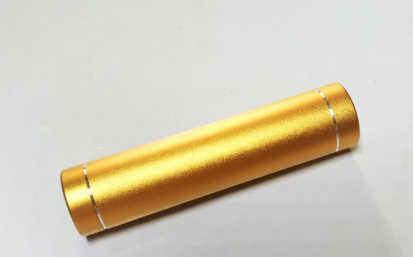
This case is mainly made of aluminum alloy, which is almost the smallest volume you can find (which is the top priority). It allows battery replacement, has an acceptable appearance, and comes at an affordable price.
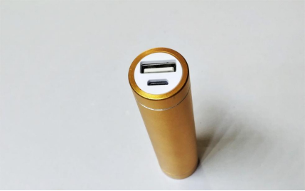
The bottom can be unscrewed to replace the battery, and you can choose the color to save costs.
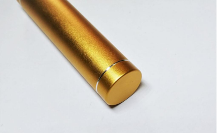
Upon disassembly, you can see that it's just slightly larger than a single battery.
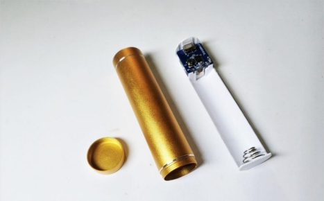
The internal components include a boost board.
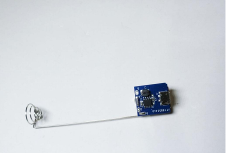
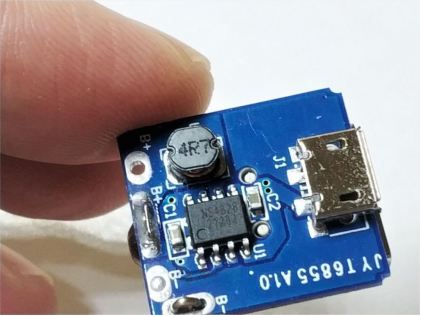
It's clear that the craftsmanship of this power bank is quite poor, and the ns4828 solution has very weak performance, with a maximum of 0.8A (practically limited to 0.6A), making it almost useless. So, the decision is to discard everything except the casing.
The first step is to develop a new boost board. Choose the single-chip ip5306 charging and discharging integrated solution, which has very high synchronous boost and buck efficiency, perfect for this limited space. The design supports both 4.2V and 4.35V, with a short circuit at R7 switching to 4.35V for charging (LED turns 4.35V). By shorting the 2-foot 47k resistor to ground, it switches to 4.35V. You can try it out if you're interested.
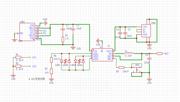
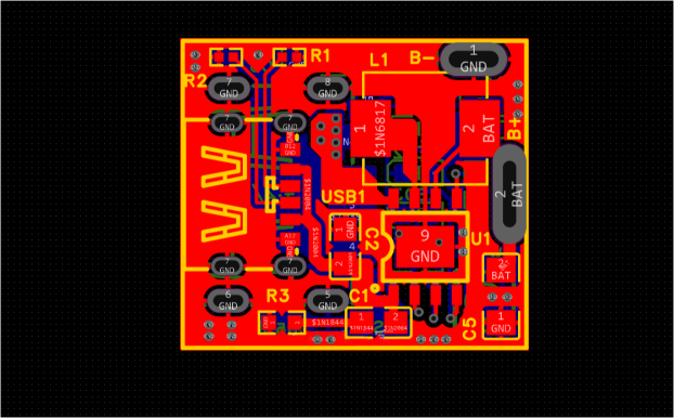
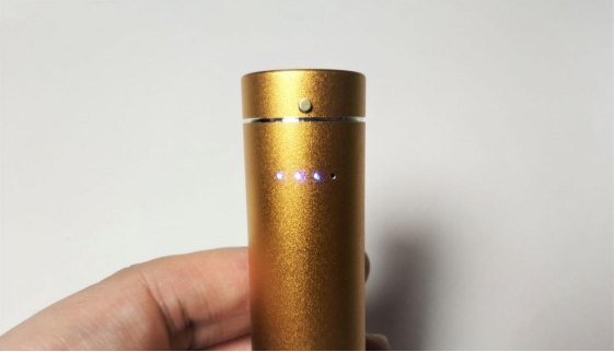
The space is very limited, but for user-friendliness, a 4-light battery level indicator is added.
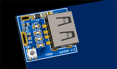
The board is made using FR-4 double-sided black oil covering with a thickness of 1.2, single frame without V-cut and no ticket holes.
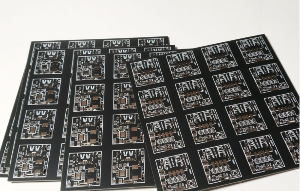
After cutting, only one piece is needed. Add solder paste and place the components.
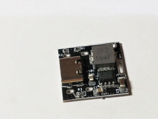
Heat and solder.
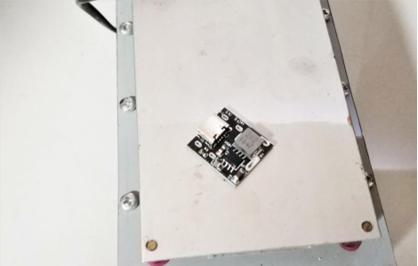
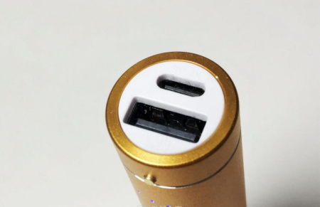
C-port uses a 6-pin connector, and the U-port uses a short 6.3mm connector.
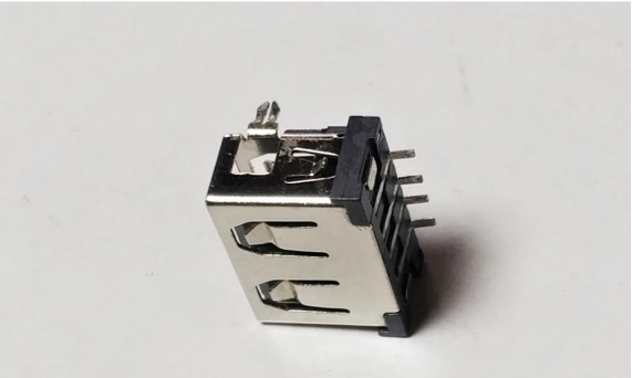
Soldering on the front side.
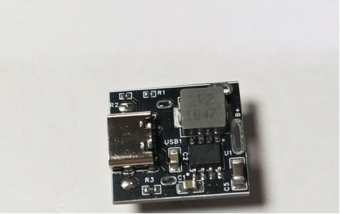
Reflow soldering on the back side for the U-port.
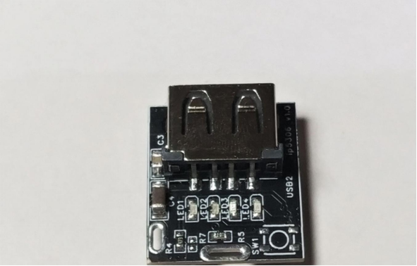
Compared to the original board, the battery level indicator is placed on the back side.
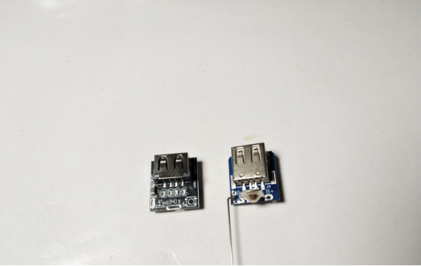
Remove the positive and negative poles.
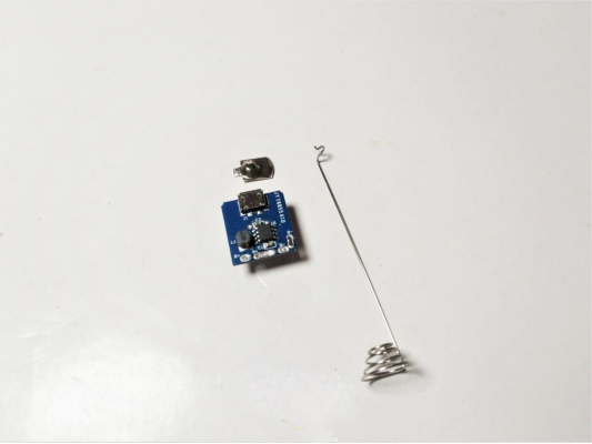
Solder and assemble, but if testing reveals that the original negative pole spring is made of iron and gets very hot (around 4A current at 12W full load), an upgrade is necessary.
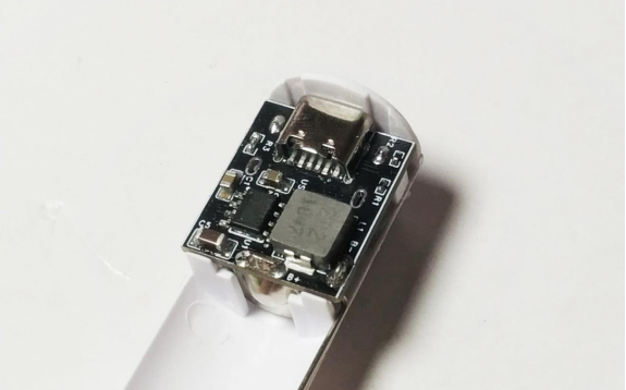
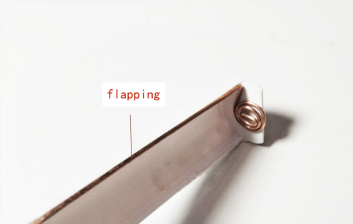
You can use a 1.2 square millimeter purple copper wire and bend it yourself. Due to space limitations, flatten the wire where it connects to the leads. After this modification, the temperature rise during full load testing is much lower.
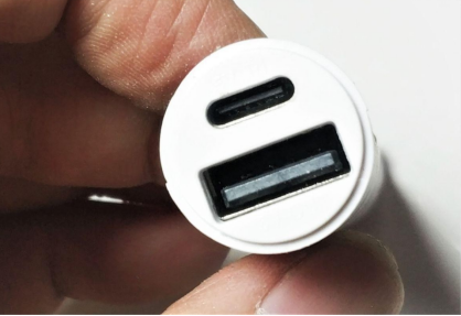
The original middle frame had a micro USB port on top, but the new board uses a C-port, so the hole needs to be enlarged and machined into a C-port shape. External cosmetic features require precision machining, and this hole is no exception—it must replicate the original effect.
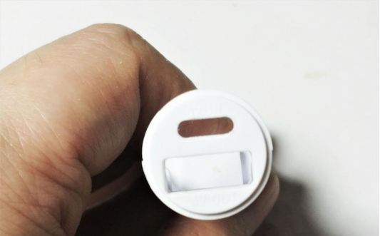
The positions of the two ports have very tight tolerances in the design, making them almost seamless.
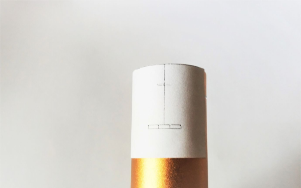
Make holes for the buttons and battery level indicator. These holes affect the overall appearance and require high precision. Any deviation will impact the entire work. To improve accuracy and reduce errors, use CorelDRAW to draw the lines and print them out to stick on the case. Internal alignment measurements must also be repeated several times to minimize deviations.
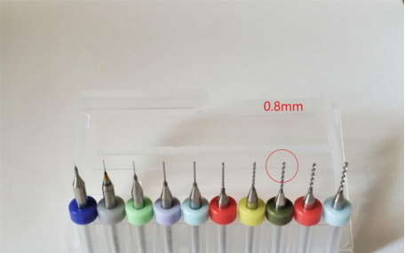
Use tungsten steel drill bits ranging from 0.1mm to 1.0mm, with 0.8mm for the four small holes (marked in red).
Precision in drilling is crucial; a slight deviation can ruin the whole project, and there's no way to remedy it. To achieve this, use a modified drill press with tungsten steel drill bits of various sizes. After drilling the small holes, make the larger hole for the button, which is 3mm in diameter.
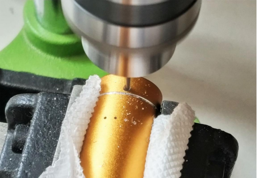
The machining is now complete, and it looks nearly perfect. The internal part has also been drilled.
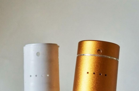
Cut a piece of black foam into a semicircle and place it here. Then, poke holes and insert optical fibers for guiding light.
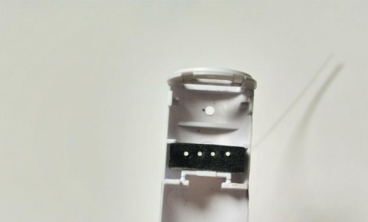
Use a rhinoceros blade to cut off the excess.
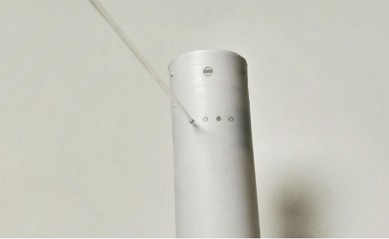
Due to the limited space, the original design had the button placed below the battery level indicator. After careful observation, it felt too close and abrupt, so it was moved to the space below the Type-C port. A micro switch was opened up, mainly for its metal button. It was carefully selected for this purpose.
Open it up to find a thin film membrane switch and a button cap.
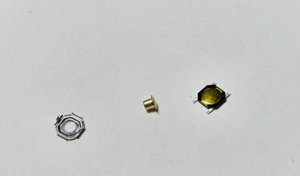
The button cap is made of copper with plating, which matches the opening perfectly. Add polyimide tape on the edges to prevent it from falling off.
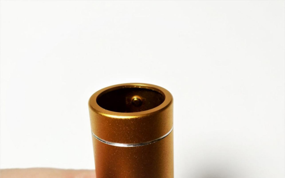
The front view with the button cap in place. It complements the case color, and the proportion with the bottom battery level opening is just right, adding a finishing touch to the overall look.
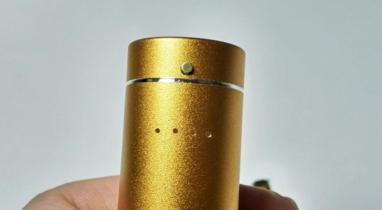
This area conflicts with the button cap, so it needs to be removed to accommodate the micro switch.
After removal.
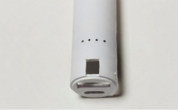
The remaining half of the micro switch is placed here, secured with black foam and strong fabric-based double-sided tape.
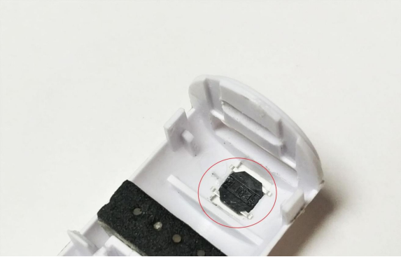
The front view shows it slightly lower than the surface.
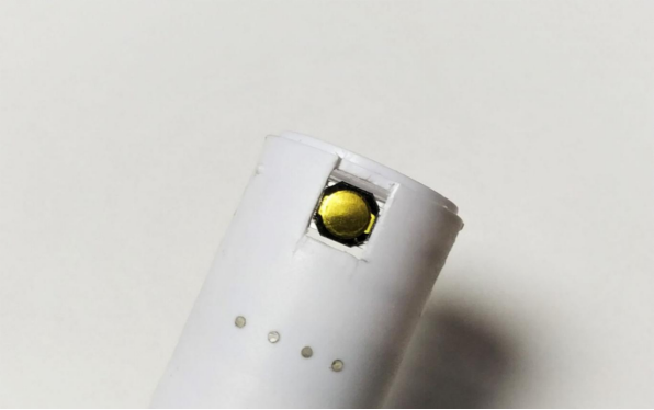
Originally, a smaller micro switch was intended for this area, requiring a force-arm conversion bracket to be made to the central area. Since the switch was moved to the top, this plan was discarded, and only flying leads were used.
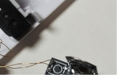
Secure it with epoxy adhesive, and once cured...
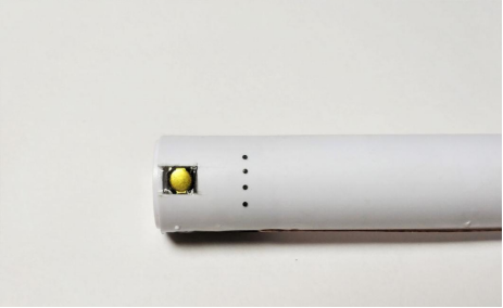
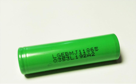
To maximize the 18650 battery's capacity, you can use an MJ1 cell or LG with a maximum capacity of 3500mAh (similar to most others in the industry). With high capacity and low internal resistance (generally 2x MR), these batteries maintain relatively large discharge capabilities even at high currents, making them suitable as power sources.
During later tests, the 2.2uH inductor was replaced with a 1uH one to reduce inductive losses slightly. However, this caused a slight increase in ripple. In such a small space, minimizing losses takes priority.
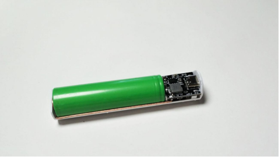
The assembly is complete.
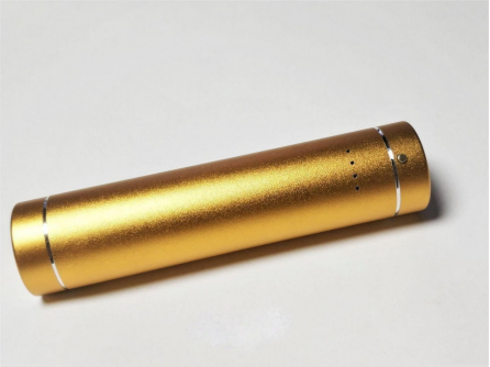
The battery level indicator lights up, and the micro switch has excellent tactile feedback, making the overall appearance quite pleasing.
Top view.
During charging tests, the current reached around 1.76A at nearly full charge, with a synchronous buck-boost charging topology, meaning that the battery-side current is already above 2A due to a charging current of 2A. This is twice as fast as the typical 4056 model, and the nonlinear charging loss is minimal. The charger supports adaptive current limiting, adjusting the maximum charging current based on the input voltage to avoid using maximum current for charging and straining small current chargers.
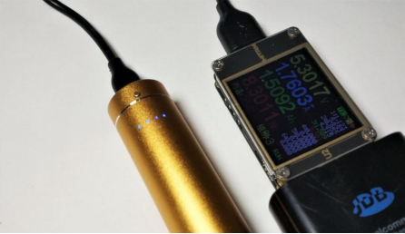
No-load performance.
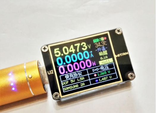
During charging tests using the BC1.2 DCP protocol, the current was around 1.7-1.8A when the phone was almost fully charged. This is due to firmware limitations in the phone, as DCP mode typically tops at around 1.8A, and the 11u DCP goes up to a maximum of 1.8A.
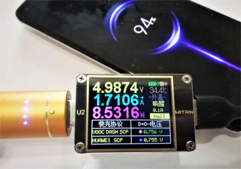
The maximum load is approximately 12W. The overall performance includes 2A charging and 2.4A discharging, with a maximum output power of 12W. This output power and current exceed the maximum value for DCP, reaching the limit of 2.4A for Type-A. The 3500mAh capacity is the largest for perfume power banks, and it can roughly charge a 3000mAh phone from zero to full once.


