
If you're thinking of buying a motorhome and modifying it, you can get an empty shell from an RV factory and design the interior water and electrical systems yourself.
For this project, you might need these modules: an energy management system with a 220V inverter, wireless remote-controlled lighting, a video surveillance system, a low-voltage power grid for charging phones and tablets, and a remote control system for devices like water pumps.
Most motorhomes integrate the control panel inside, which takes up a lot of space. If you prefer a different approach, you can opt for wireless communication for complete vehicle control and data transmission. You can create a small PDA to act as a remote control, managing all the devices in the motorhome and viewing their status data.
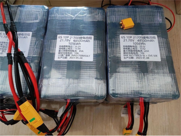
Let's start the design with the energy management aspect. First, consider the battery part. Lead-acid batteries are ruled out, and you can choose LG's M50LT or Yiwei's 50E, both 21700 cells with 1000 cycles of lifespan. Assemble them into 6S10P battery packs, where each pack contains a single cell, allowing you to discard only the faulty cell rather than replacing the whole pack. Use flame-retardant foam double-sided tape to separate the battery cells during assembly.
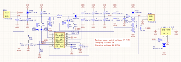
Next, focus on the solar charging aspect. High-power solar panels in the market typically have an 18V voltage, while the battery pack is fully charged at 25.2V. You'll need a boost or buck-boost MPPT charging solution. Consider trying the CN3306 solution from Yun Electronics for its simplicity and practicality. Plan to use one CN3306 module for each 120W solar panel to charge the battery pack. Multiple modules can be integrated into the energy management system to monitor the output power of each solar panel.
During the design process, pay attention to specific parameters. Ensure that the charging voltage is slightly lower than the 6-series lithium battery's 25.2V cutoff voltage to avoid overcharging if there's a slight imbalance in the cells. Choose an MPPT tracking voltage slightly lower than 18V for better performance. Connect the SHDN pin so that the energy management module can control the charging module and halt charging when necessary.
The final version of the schematic and design is shown below.
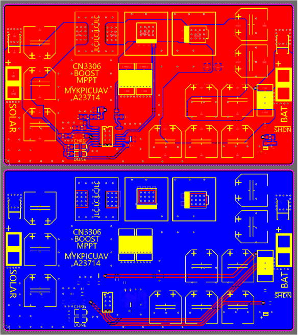
To improve the power devices' heat dissipation, you can design the backside of the board with a whole layer of silkscreen and solder mask, preventing solder from leaking through the holes.
The finished product is shown below, and the heat sink at the bottom has also been enlarged and thickened.
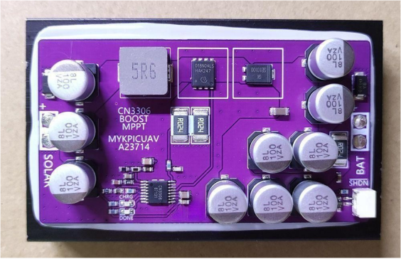
Sampling part of the resistor, taking into account the board work temperature varies greatly, so the use of 0.1% precision 25ppm / ℃ film resistors, film resistors using magnetron sputtering process production, consistency, precision, temperature characteristics of a lot better, thick film resistors are screen-printed, precision and consistency will be worse.
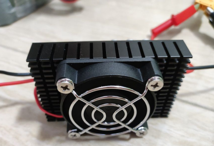
The back of the board to add a small 24V cooling fan, and the solar input in parallel with the solar input, there is a power input before turning, and the fan rated voltage is higher than the solar panel operating voltage, but also will not be fully loaded, a little bit of breeze can be convection cooling a little bit can dramatically reduce the temperature of the heatsink.
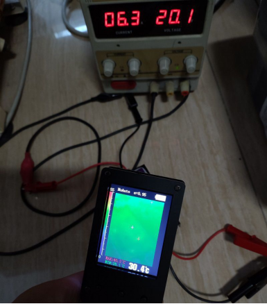
For the board, it operates at 20.1V and 6.3A input for five minutes, with only a slightly warm sensation and a maximum temperature of around 41 degrees Celsius (at an ambient temperature of 27 degrees Celsius), which is perfect.
If you feel that vias should not be drilled on the pads, it won't be an issue as long as you cover the bottom layer with a complete layer of silkscreen and solder mask to prevent solder leakage. Additionally, this design will help improve the power devices' heat dissipation.
Below are the Gerber files for the layout:
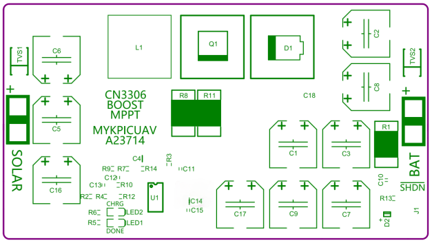
Schematic, BOM table are as below:
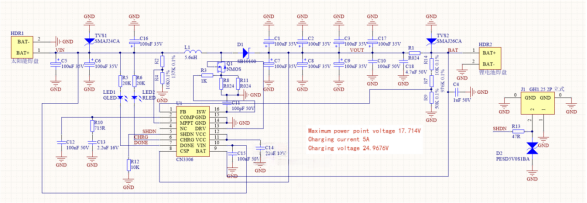
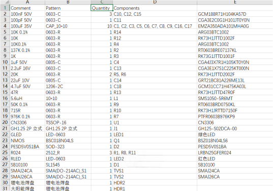
Please note the following points while working on the project:
1. The materials can be relatively expensive. If you want to use industrial-grade components, you can refer to the schematic and choose suitable options. However, for ceramic capacitors, avoid using materials like X5R or Y5V; choose at least X6S or preferably X7R.
2. This design is intended for a 5A output current. If you require higher power or need to adjust the MPPT voltage or output voltage, you can modify the resistor values accordingly using appropriate tools.
3. The design takes into account extreme conditions, so it's essential to choose suitable resistors for heat dissipation, especially for the current sensing resistors.


