
Revolutionizing automotive power sources, a cutting-edge project employs super capacitors to craft a dynamic car auxiliary supply. With a sleek casing measuring 250x80x85, this innovation maximizes internal space through ingenious curved board design. Seamlessly integrating an automatic voltage module and a precision relay, this custom creation is geared for efficient and versatile energy management. The journey unfolds with a deep dive into the intricacies of design and execution, showcasing the harmonious fusion of technology and automotive prowess.
Let's start by examining the finished product, which features a casing measuring 250x80x85.
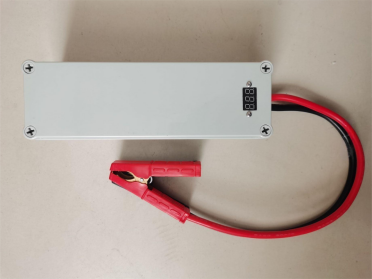
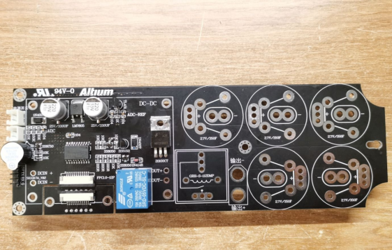
Given the limited space within this casing, the aim was to maximize space utilization. The board has internal rounded corners that snugly fit within the casing, utilizing the pre-existing fixing holes in the casing.
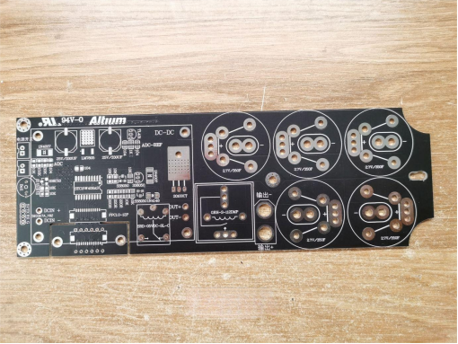
The automatic voltage boost/buck module utilizes the LT8705 design for its compact size and high efficiency.
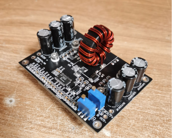
Since this board is self-designed, merely toggling the positive terminal suffices to switch between charging and discharging. The relay used is the GRH-S112DMP model.
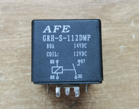
Upon testing, the contact resistance of the relay showed variable values, which could be attributed to minor protrusions on the relay contacts.
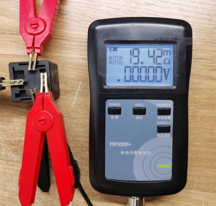
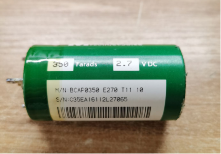
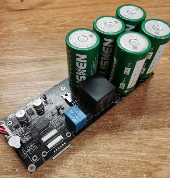
For the Farad capacitor, a 2.7V/350F unit salvaged from a Force God capacitor was employed. The board is also compatible with China Railway's super capacitors. Capacitor details and codes are provided.
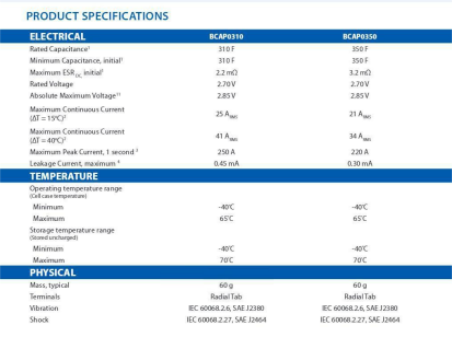
Official data indicates that the 310F capacitor's internal resistance is better than that of the 350F capacitor.
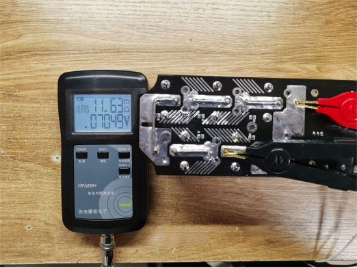
In practical tests, the internal resistance of this capacitor is approximately 2mΩ.

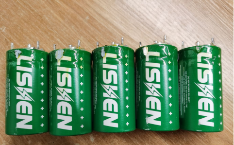
Five capacitors are connected in series, requiring individual resistance matching. However, the basic parameters among them are mostly consistent.
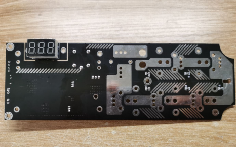
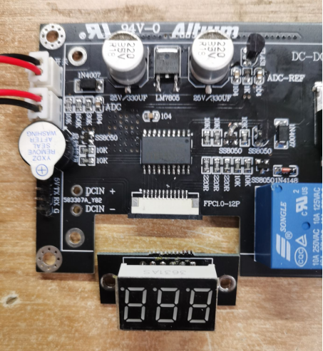
The board maintains a dual-layer design: the top layer hosts the automatic voltage boost/buck module, while the bottom layer handles control. The display board can be detached using a ribbon cable for connection elsewhere and then soldered in place.
The digital display is situated on the back of the board, indicating voltage, ignition countdown, and other information. Each capacitor features a 1K resistor for discharge purposes. If left fully charged and unused, they would discharge in roughly 2 days. Charging occurs just before use, eliminating the need for long-term storage with uneven voltages. Hence, the balancing circuit is omitted.
With the capacitors and relay in place, the choice of 5-series capacitors over 6-series is clarified. Primarily, the total capacity of 5-series capacitors is greater, prolonging discharge time. Additionally, the internal resistance of the 5-series is lower, boosting instantaneous discharge capacity. Furthermore, the official PDF states a maximum voltage endurance of 2.85V for each capacitor. With 5 capacitors at 2.85V, the total is 14.25V, adequately meeting car starting voltage requirements.
The internal resistance of the capacitor array is 11.63mΩ.
Removing the display section involves drilling holes in the casing.
Two copper pillars are added to adjust height, aligning them flush with the casing.

Initial adjustments are made to the output voltage of the automatic voltage boost/buck module, with finer tuning after installation.
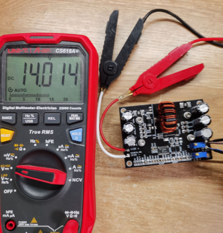
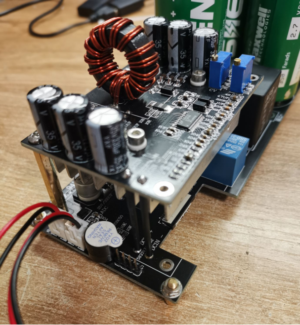
Four 2.5-square millimeter hard copper wires are soldered to the automatic voltage boost/buck module for electrical connection.

Heat shrink tubing is applied to the copper wires, with the heatsink nearly touching the charging relay.

Copper pillars are attached to the board. Although four could be used, the four copper wires provide ample stability, so two are omitted.
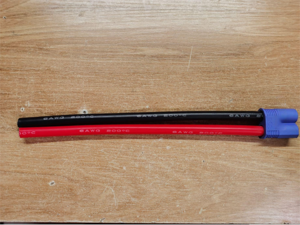
A 6AWG (approximately 14-square millimeter) output wire is connected, with an EC8 aviation plug soldered on.
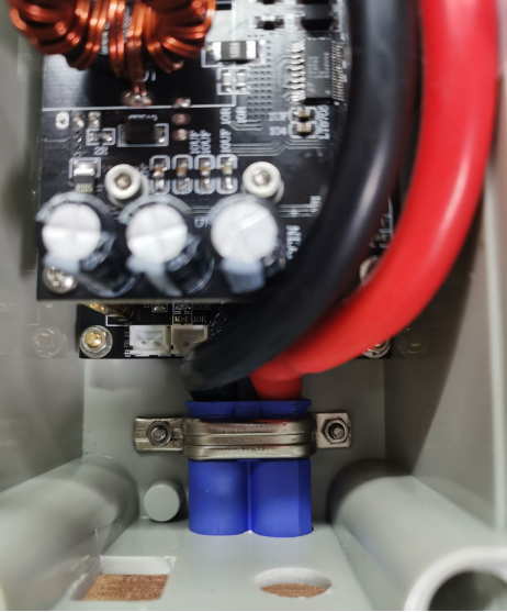
A custom fixture using old instrument clips secures the EC8 plug in place perfectly.
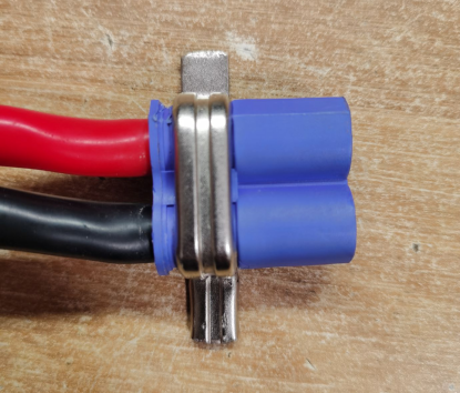
The EC8 plug is now securely affixed to the casing, without any wobbling.
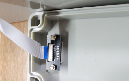
An FPC ribbon cable is used for the display connection.
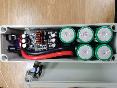
Before installation, here's the overall appearance.
Additionally, a charging clamp is fashioned for this purpose. Due to the limited 5A maximum current of this power source, the module enters MPPT mode when charging.
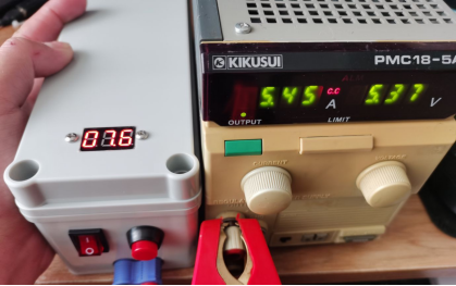
With a reverse current protection diode on the board, the module's output voltage must be adjusted to 14.7V to charge the capacitors to 14V.
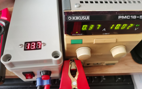
Charging is completed in 6 minutes from 0 to 14V, subject to the power source's output limitation. If charged using a battery, 3 minutes would likely suffice.
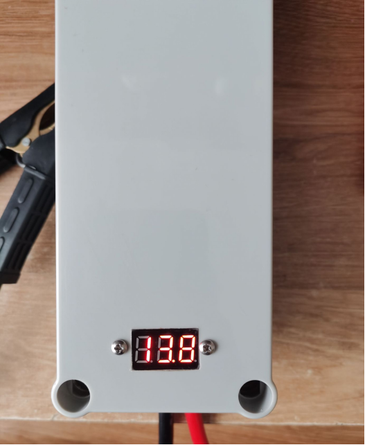
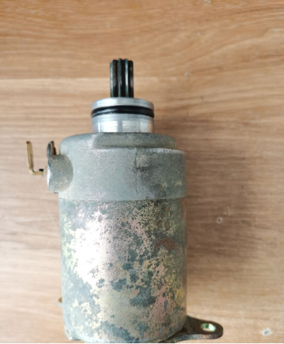
This setup was tested with a kick-start motorcycle's starter motor. The initial current upon starting reached 40A, which subsequently dropped to 14A when running.
Regarding starting current, taking a Volkswagen starter motor as an example, with a power of 1.1KW and a 12V system, the starting current is approximately 92A. In this setup, considering the internal resistance of the capacitor (12mΩ), relay (20mΩ), and other miscellaneous wires, the total resistance is about 100mΩ. With 12V divided by 0.1Ω, the current is 120A, more than sufficient to start vehicles up to 2.0 liters.


