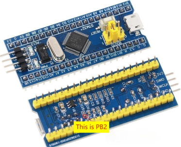
If there Unlock the potential of keyboard integration with just an STM32F103C8T6 development board and a standard laptop keyboard. This guide presents a straightforward method to interface a laptop keyboard's 8x16 matrix with the development board's PA0~PA7 and PB0~PB15 pins.
Please note a specific consideration: on this board, the PB2 pin is not externally accessible. However, it's worth mentioning that BOOT1 is connected to PB2 through a resistor. This distinction is clearly highlighted in the accompanying image.

Before delving into the implementation, it's essential to introduce the relevant firmware components:
· "stm32f103.keyboard8x16.bin": This firmware corresponds to a conventional keyboard configuration.
· "stm32f103.keyboard8x16.matrix.bin": Designed for matrix testing, this firmware provides an invaluable tool for verifying connections.
Upon flashing any of the firmware variants and establishing a USB connection with your computer, an identifiable keyboard device will materialize. Engaging the CapLock key will trigger the illuminating LED on the development board—a visual confirmation of successful linkage.
By flashing the "matrix.bin" firmware and subsequently connecting the board to your computer, you can initiate the process. Open a text editor, position the cursor, and engage in a hands-on test. Through the strategic short-circuiting of combinations between PA0~PA7 and PB0~PB15, you will observe the matrix row and column numbers materialize within the text editor. This particular firmware serves as an invaluable asset for diverse testing scenarios.
In the interest of streamlining assembly, it's advisable to address thickness concerns. This entails the removal of vertically-oriented header pins from the development board. The removal of all but the BOOT0 and BOOT1 pins doesn't preclude SWD port usage for future downloads.
Procuring suitable connectors for cables can indeed present challenges. A pragmatic solution involves utilizing thin double-sided adhesive to secure tinned enamel wires to the designated connector points on the header. Subsequently, exert pressure using screws and durable plastic components to ensure secure adherence. The addition of soft padding or elastic materials contributes to optimal stress distribution and consistent contact.
Notably, the self-contained laptop keyboard boasts a slim profile, necessitating fixation onto a wooden or acrylic substrate.
Incorporating grooves within the board facilitates the accommodation of the STM32 development board—reducing thickness constraints. Subsequent to positioning the components, initiate the wiring process.
The simplicity of this setup is predicated on shared foundational principles across various keyboard types. Analysis of available keyboards, encompassing laptop and desktop variants, underscores their shared 8x16 matrix architecture. While wire sequences may differ, the underlying framework remains consistent—albeit occasional exceptions.
Absence of comprehensive documentation need not impede progress. To discern the dual-grouping structure of 8 rows and 16 columns from a potentially larger wire assembly, meticulous examination of wire terminations is recommended. Post-grouping identification, commence the interconnections. Start with a row wire and a column wire, interfacing the keyboard, and initiate testing using a text editor or dedicated software. Iteratively refine the connections until the desired key response alignment is achieved—a process that's more intuitive as familiarity grows.
Supplementing the core setup are three open-drain output states:
· PC15: NumLock
· PC13: CapLock
· PC14: ScrollLock
Initial implementation of this keyboard integration may require an investment of time and effort. However, subsequent endeavors benefit from accumulated expertise. The outcome—an elegantly slender and compact keyboard solution—eliminates concerns associated with mechanical responsiveness, elevating the user experience significantly.


