
For low power, ensure isolation, and directly use relays for transmit-receive switching. If PIN tubes seem expensive now, you can opt for commonly used relays. Functional modules like M57729L and RA30H4047M are available. Let's start building a handheld RF power amplifier as a DIY project.
This external power amplifier setup is straightforward. There are two control methods: push-pull control involves using RF voltage from the handheld transmitter to activate the amplifier, and the CAT control is similar to shortwave radio. Synchronized signals from the handheld control it, eliminating the need for meticulous electromagnetic isolation required in the first method. On the transmit-receive conversion side, two methods exist: PIN tube conversion, which is costlier but more effective and commonly seen in established manufacturers' devices, and relay conversion, common in smaller factories due to its cost-effectiveness. This project follows the relay conversion approach.
First, create the circuit board.
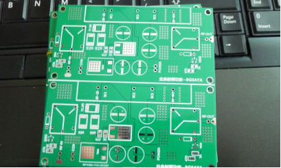
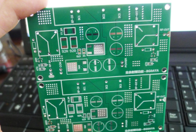
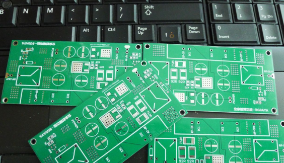
Cut and assemble, making extra boards is advisable for a worry-free DIY experience.
Amplifier module.
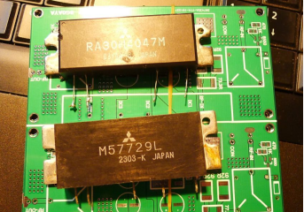
Identify components and assess the design's suitability.
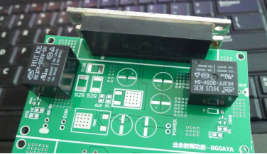
There are various ways to install the amplifier; choose what suits your needs.
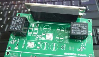
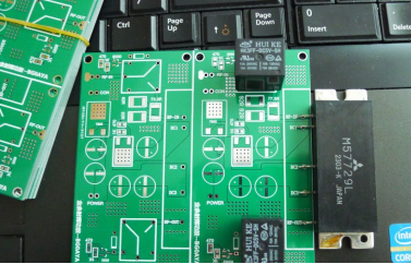
Start by soldering the power supply section, test control functionality, then proceed to solder the amplifier.
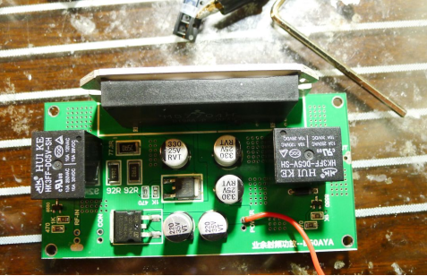
After circuitry is soldered, move on to creating and testing feed lines. Use Teflon wire for testing, simple connections will suffice as it's for testing purposes.
Solder smaller feed lines like N-connectors.
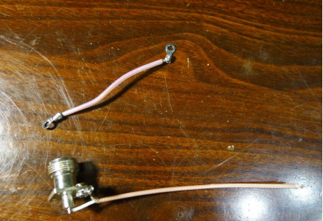
Use -5 Teflon and M connectors.
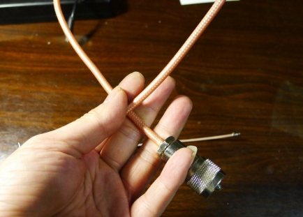
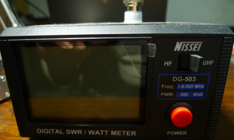
A power standing wave ratio (SWR) meter for testing.
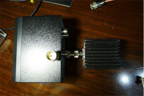
A 50W dummy load.
The final product should look like this.
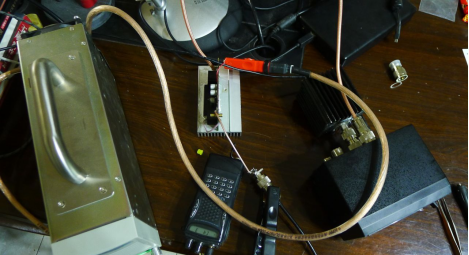
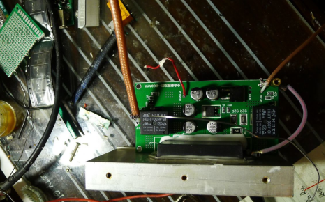
Note: Explanation of principles and circuitry is provided below.
Creating a radio frequency power amplifier differs from audio amplifiers. RF amplifiers generally involve a staged approach: RF-IN, first-stage amplification, second-stage, and so on up to RF-OUT. Different manufacturers have varying amplifier designs. For example, the M577XX series I'm using employs a uniform voltage for push-pull, while other manufacturers might control the first-stage power adjustment. The following explanation uses the M577XX series for circuit illustration.
Start by understanding the model, its normal power supply voltage, frequency characteristics, and power input/output features. Let's take the M57704H as an example.

According to official documentation, this module operates within the 450-470MHz range, with a 20MHz tolerance. It can be used within 430-490MHz, and even 420MHz with degraded characteristics. It typically operates at 12.5V, outputting 13W. Refer to the official documentation for typical operating characteristics.
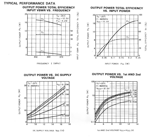
The module can actually output up to 85W, but this significantly reduces its lifespan. Besides the specifications mentioned earlier, frequency characteristics are crucial.
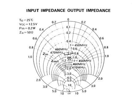
A frequency response graph displays the module's frequency characteristics. Amateur use generally focuses on typical values. If the graph isn't understandable, it doesn't hinder usage.
To understand the module's pins, consult this diagram.
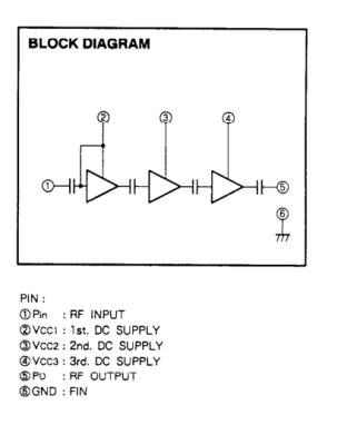
There are five pins: 1 for input, 2, 3, and 4 for power supply, and 5 for output. The backplate is ground. The module has 3 amplifier stages, pushing sequentially.
With these insights, you can begin designing.
Consult the manual for the module's maximum input power, typically 0.4W.
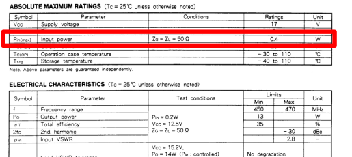
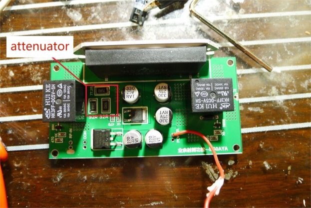
Handheld radios generally output around 4W, which would damage the module. An attenuator is needed, typically composed of resistors with values like 75 ohms and 91 ohms.
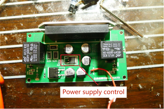
To avoid self-oscillation or transmission interference, control the power supply. Only with control will the module operate.
As an external power amplifier, both amplification and handheld sensitivity must be considered. A separate transmit-receive switch is needed, ensuring distinct paths.
Two control methods exist: using PIN diodes or relays.
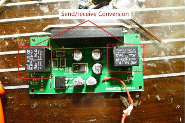
In summary: attenuate the output, control the power supply, and implement transmit-receive switching. Mastering these aspects allows for DIY amateur power amplifier creation.
While creating a high-frequency amplifier is relatively simple, designing it effectively for optimal performance is challenging. The next section discusses this circuit's drawbacks.
1. PCB impedance matching hasn't been tested. Many RF circuits require impedance matching for 50 ohms output. Designing this requires specialized simulation software and expensive testing equipment.
2. Transmit-receive conversion: PIN diodes are superior but expensive. Relays have higher losses, and most signal relays online are subpar. Used, reliable signal relays are costly, but ordinary relays suffice for DIY.
3. SWR protection is recommended.
4. Bandpass filters reduce electromagnetic pollution by allowing specific frequencies to pass through.


