
If you want to create a power supply similar to Kikusui's power supply, you can follow this process, from researching the circuit to designing the board and verifying the functionality to make one yourself.
Start with the PCB (Printed Circuit Board). The size is 9x20cm, and all the basic functions are integrated onto it.
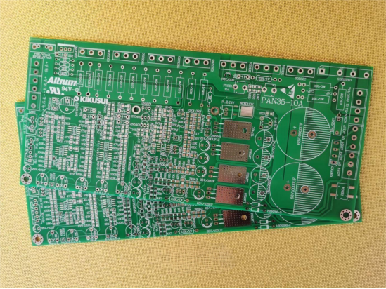
Verify the functionality with purchasable components. First, tin one side of the solder pads to facilitate SMD (Surface Mount Device) soldering.
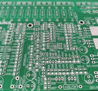
Solder the SMD components.
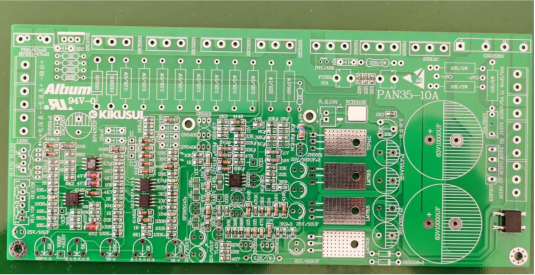
Solder the through-hole components as well (do not solder the large filter capacitor to avoid blocking the power transistor mounting screws).
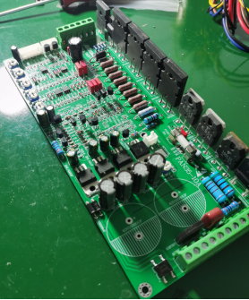
For current sensing, use a high-precision OP37G operational amplifier along with a high-precision current-sensing resistor.
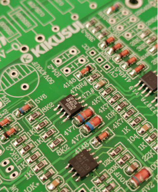
Decouple capacitors.
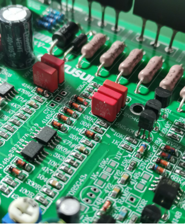
Use high-quality through-hole resistors, such as Fukushima Futaba or Panasonic with copper legs.
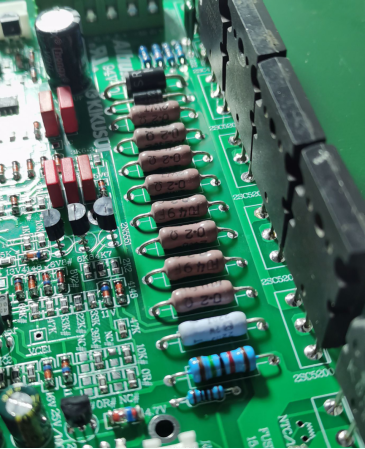
Detailed view of the precision current-sensing resistor.
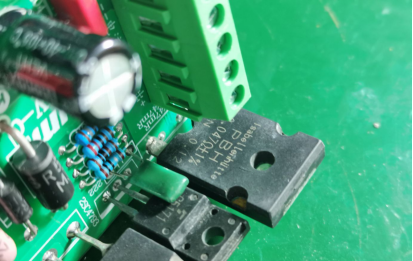
Use four Toshiba 2SC5200 power transistors, a U-shaped heat sink with a length of 20cm for higher heat dissipation efficiency.
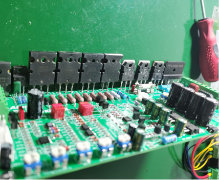
Make markings with a marker pen first to facilitate positioning before drilling holes. Apply some oil before tapping threads to make threading smoother.
After tapping threads, install screws (try M3 screws).
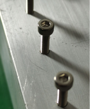
Attach the heat sink, apply thermal grease behind the larger transistor, and add mica sheets.
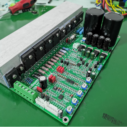
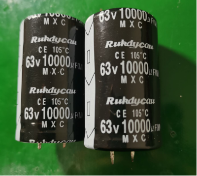
For filtering, use two parallel-connected 63V 10000uF Ruby capacitors.
Once soldering is complete, according to the board markings, first test the pre-regulator section with a dual 18V power supply to ensure it functions correctly. This prevents blowing up the filter capacitors when powered on for the first time.
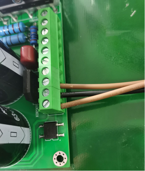
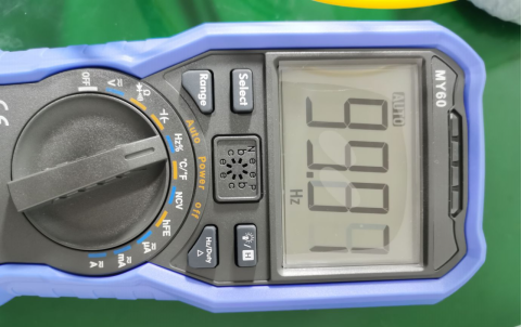
Test the test points reserved on the board; the oscillation frequency is 100Hz, which is normal.
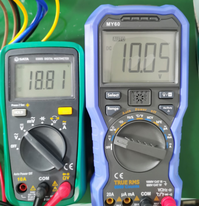
Connect various power sources, connect the inductors in series. The inductors are taken from a variable frequency air conditioner, labeled as 8mH but measured at 5mH.
Before powering on, make sure to connect a potentiometer, or else the output capacitors might blow up. After connecting the potentiometer, adjust the output to normal (the left multimeter measures the pre-regulator output voltage, and the right one measures the output voltage). Since it's an unloaded state, the pre-regulator output is slightly higher, creating a 7V difference with a load, ensuring stability and low power transistor heating for efficiency.
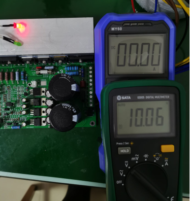
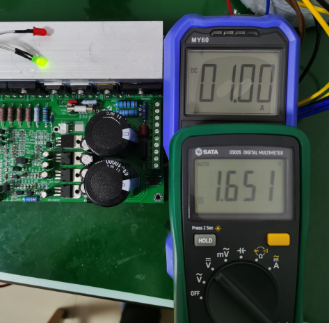
Test for accuracy and stability; the red light is for constant voltage, and the green light is for constant current. The multimeter above measures voltage, and the OWON multimeter below measures current. The load uses Kikusui PLZ electronic load.
Constant voltage output is 10.06V, with a load of 0A.
Constant current is set to 1A, and the output is 0.99A; the voltage drop is negligible.
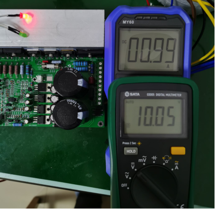
As the current increases to 1A, it enters constant current mode, and the voltage drops, and the cross-flow light comes on.
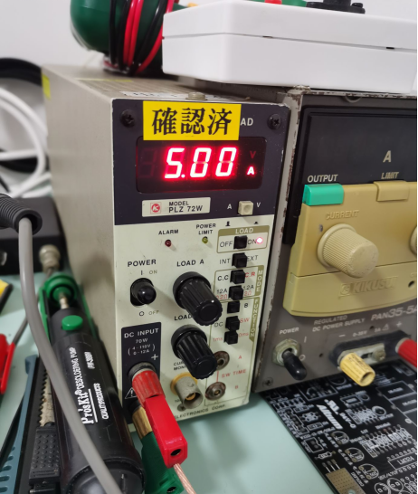
The electronic load operates at 5V5A for more than 10 minutes. Since the board is exposed, it cools naturally, and the temperature on the heat sink is about 40 degrees, not too hot.
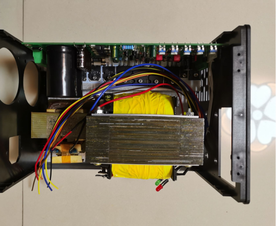
The transformer is quite heavy; originally, it outputs 30V12A using dual-winding and series connections. There are two parallel-connected double 15V AC windings added, as the iron core has been removed. When powered, the outermost iron core vibrates like a doorbell.
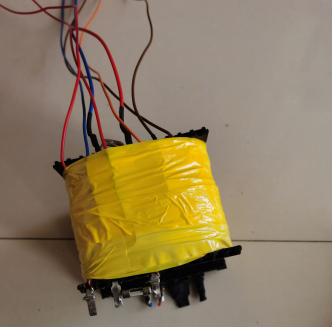
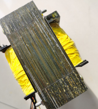
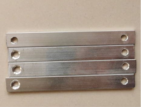
Use aluminum angle brackets to secure the vibrating piece. Cut them into four pieces of equal length and drill holes.
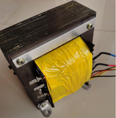
Now, it looks much better after installation; although the transformer still makes noise, it no longer vibrates.
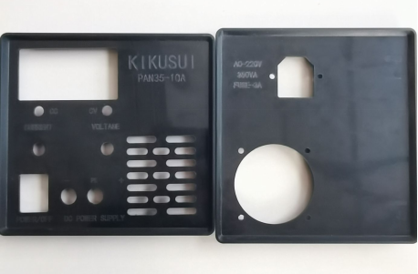
The chassis is made of aluminum with a plastic panel. Remove the panel, design the layout and hole positions in advance, and then use a CNC machine for processing.

Install the chassis. If the chassis height and width are very close, and you accidentally install it the wrong way, you can rotate it 90 degrees to the left and cut a fan hole on the left side of the fan. Install the fan and place the board and transformer inside. The chassis is quite compact due to its small size.
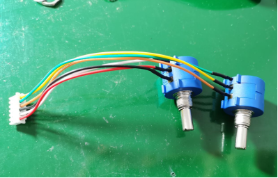
Use a potentiometer inside; you can use a multi-turn potentiometer from KOB for this purpose or a 3590S potentiometer.
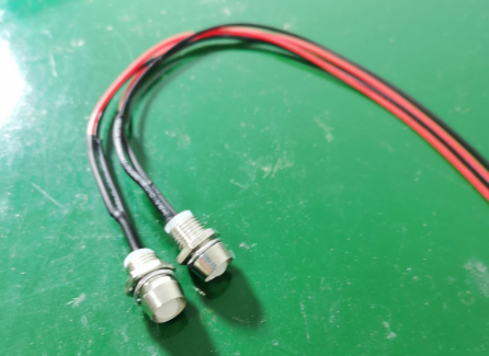
Place the indicator light with a metal cap inside.
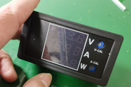
Place the voltmeter inside (if it's a three-color display with power but scans slowly, the display may be discontinuous, making it difficult to adjust to the desired voltage).
Connect the terminal blocks, assemble everything tightly.
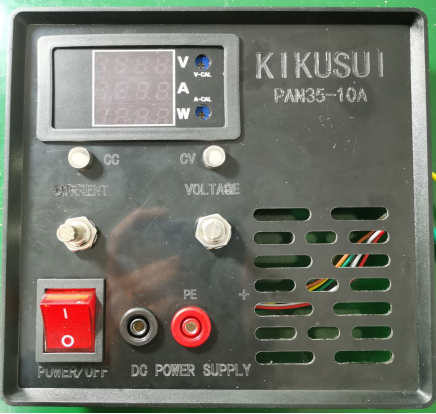
Finished product.
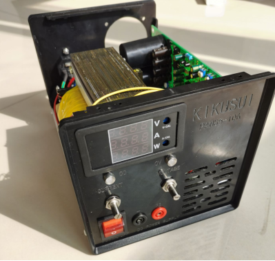
The fan width left is 2cm; if you don't find a suitable one, you can install it later. Cover any wrongly drilled holes with fan covers.
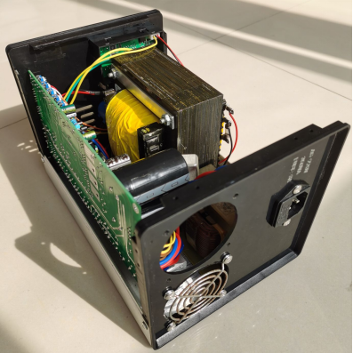
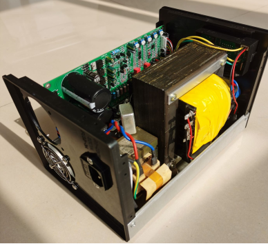
Limit the maximum output voltage to 36V, and the voltage for 24V output remains stable without fluctuations.
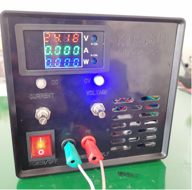
The maximum current is limited to 10A. The jumper clips are made of iron, resulting in a higher resistance, causing a voltage drop of about 0.58V when short-circuiting the output. The jumper clips get hot when short-circuiting the output.
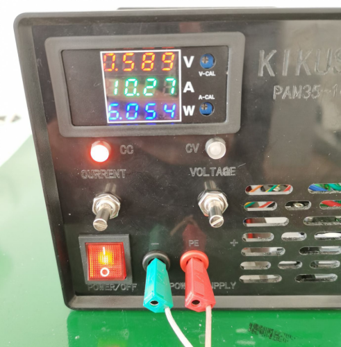
With that, the power supply creation is complete. Since the potentiometer knob is slightly smaller than the shaft, you can purchase a pair online to fit properly.


