
Lithium-ion batteries represent the most pervasive form of battery technology in contemporary applications, spanning from commonplace devices like Bluetooth earphones to the more substantial power requirements of electric vehicles. Typically, individual lithium-ion cells maintain a voltage level around 4.2V (nominal). In instances necessitating higher voltage outputs, it becomes imperative to interconnect multiple cells in a series configuration, forming a high-voltage battery assembly. (It's worth noting that boosting solutions are primarily suited for low-power applications.) For example, a common 12V cordless drill necessitates the alignment of three cells in a series arrangement. In such series circuits, each cell possesses distinct internal resistance characteristics. Consequently, cells with higher internal resistance tend to degrade prematurely. To mitigate this issue and maintain uniform voltage levels across cells within the battery pack, the integration of a balance charger is essential.
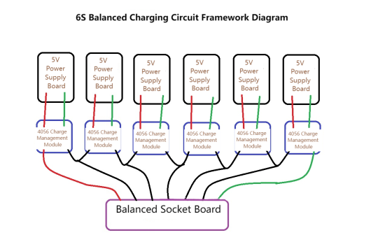
First, let us outline the schematic diagram for the balance charger. We shall employ a modular design, featuring a straightforward circuit layout: six 220V-to-5V power supply boards, six TP4056 charging management modules, complemented by an array of wires, switches, balance connectors, and ancillary components.
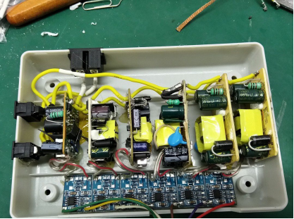
For the enclosure, we will employ a TZ7204 telephone line junction box. After due deliberation, we have chosen to orient the six boards vertically, a configuration that impeccably matches the available spatial constraints.
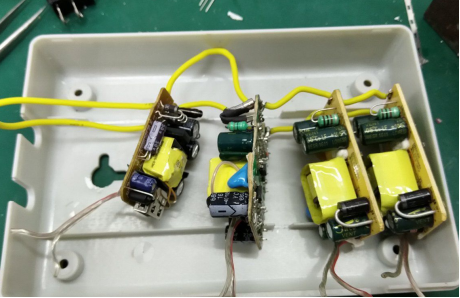
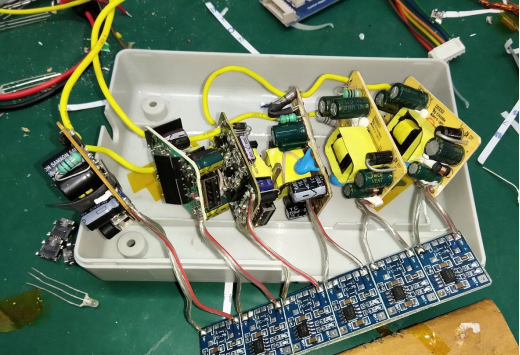
The soldering process is omitted here, but a visual representation below illustrates the meticulously soldered connections.
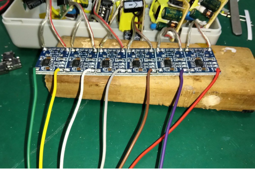
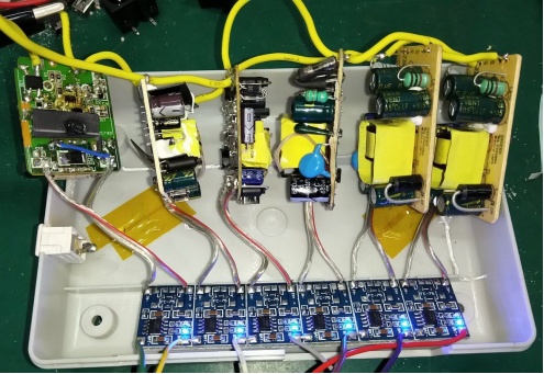
Within the output wires emanating from the TP4056 modules, the middle five wires function as common conductors. The wire on the left serves as the positive terminal for the left TP4056 module, whereas the one on the right acts as the negative terminal for the right TP4056 module.
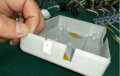
Devise a strategy to incorporate two switches into the charger's design, each overseeing three channels. When charging exclusively three cell strings, the remaining three channels can be deactivated to conserve power. Let us proceed to drill holes for the switches.
Link all six channels to a single switch for the initial testing phase. Successful execution of this step should result in the illumination of indicator lights.
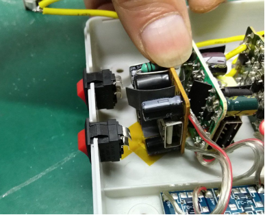
Placement of the switches involves a meticulous consideration of pin bending and appropriate spacing in relation to the circuit board.
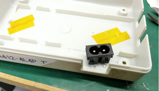
Given the surplus space at the rear of the enclosure, we intend to install an "8"-shaped holder. This pragmatic addition will facilitate the neat storage of power cables when not in active use.
All components associated with the high-voltage section have been securely interconnected, ensuring optimal safety measures.
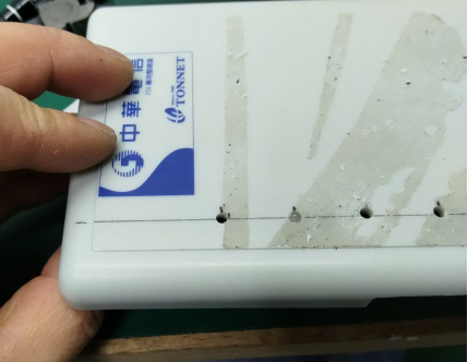
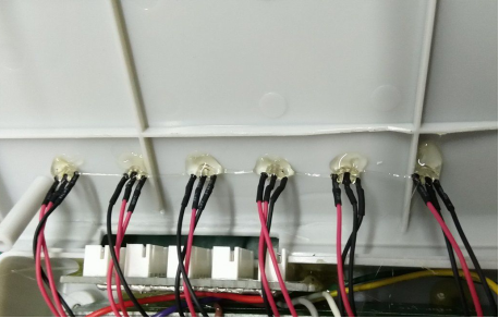
Perforations have been meticulously crafted in the cover to accommodate the charging indicator lights. Following the demarcation of lines, we shall employ a 3.0mm drill bit to create six apertures.
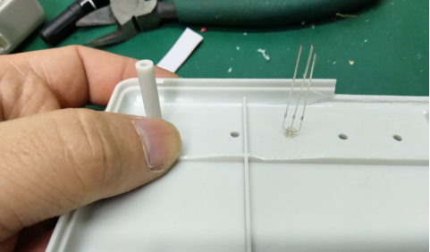
Subsequently, LEDs will be inserted into these openings, and wires will be soldered accordingly, with the soldered joints shielded by heat shrink tubing for added protection.
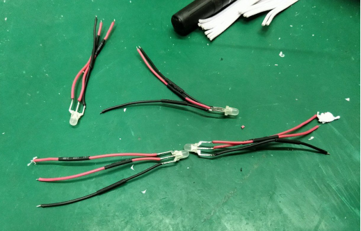
The next step entails soldering all six indicator lights to the TP4056 boards, followed by the attachment of the balance connector board. A preliminary battery insertion will affirm the charging process, with the red light signifying active charging.
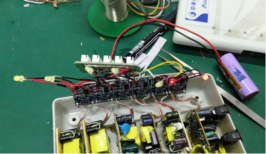
To provide access points, openings have been introduced in the outer casing. The board assumes a vertical position within this designated area. Notably, due to concerns regarding the reliability of hot melt glue, we have opted to introduce an isolation board, further fortified by 704 adhesive. This adhesive demonstrates exceptional resilience against both high and low temperatures and maintains an enduring bond over time.For insulation purposes, we have introduced an 0.8mm PCB blank as an insulating spacer between the two batteries, inserting and securing it with 704 adhesive. This approach effectively separates the power supply board from the insulating spacer.
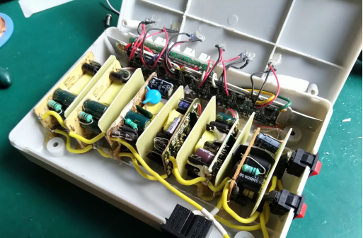
Furthermore, an aluminum plate has been affixed to the rear of the TP4056 modules, a measure designed to enhance heat dissipation efficiency.
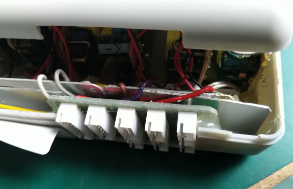
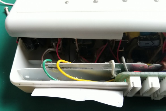
A focused view of the interface board reveals its intricate configuration.
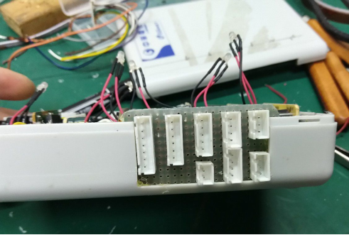
To fortify the indicator lights, a layer of adhesive has been meticulously applied.
Finally, the cover is secured, and, if necessary, we can consider designing labels to delineate interfaces. To further enhance stability and protect surfaces, rubber feet have been added to the bottom surface. The resulting product is depicted in the accompanying visual.
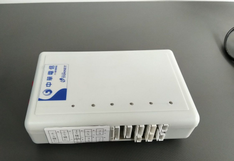
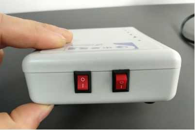
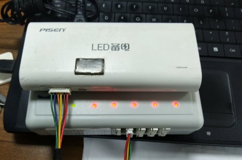
The charger's main body registers a weight of 260g, and when coupled with the power cable, it totals 323g. This configuration stands poised to facilitate the charging of a laptop as a reliable "UPS" (Uninterruptible Power Supply). Upon connection, users will observe five red indicator lights and a solitary green light, signifying one inactive channel.
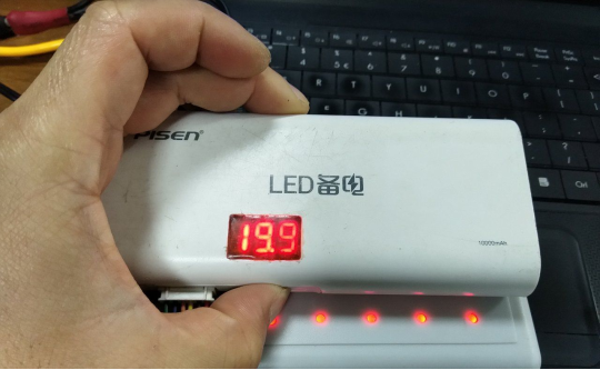
At present, the voltage reading stands at 19.9V, indicative of an ongoing charging process.
The charger has achieved full charge status, as evidenced by the illumination of all green indicator lights.
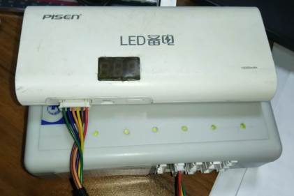
The power bank exhibits a voltage level of 21.1V, corresponding precisely to the cumulative voltage of five cells at 4.2V each, resulting in a total of 21V.
END.


