
This comprehensive guide presents an official procedure for transforming the Micro-USB charging port of a wide range of electronic devices into the modern Type-C interface. This modification ensures that your device remains relevant in an ever-evolving tech landscape, eliminating concerns about outdated charging ports when acquiring new electronic equipment. Below, we provide a detailed and accessible step-by-step process for this essential upgrade.
Procedure:
Required Tools:
· Multimeter
· Soldering iron, leaded solder, flux paste (preferably with lead)
· AB glue (modified polypropylene resin adhesive)
· Tweezers, screwdriver, double-sided adhesive, small knife
Materials Needed:
· Type-C female connector (surface-mounted, 6 pins), available for around 30 cents
· 0603 SMD resistors, 5.1kΩ
· Fine wires
Procedure:
1. Prepare the Type-C Connector:
· Obtain a 6-pin Type-C surface-mounted female connector.
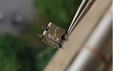
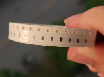
· Retrieve two 0603 SMD resistors, each rated at 5.1kΩ.
2. Understand Pin Definitions:
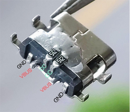
· Familiarize yourself with the six pins on the Type-C connector: two ground pins, two positive pins, and two CC (Configuration Channel) pins for Power Delivery (PD) handshake and orientation detection.
· Ensure the two CC pins are connected to ground with a 5.1kΩ resistor to prevent issues with PD chargers.
3. Soldering the Resistors:
· Use flux for smoother soldering. Leaded solder is recommended for better handling.
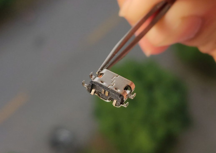
· Set the soldering iron temperature between 330 and 350 degrees Celsius.
· Connect one CC pin to ground using the SMD resistor.
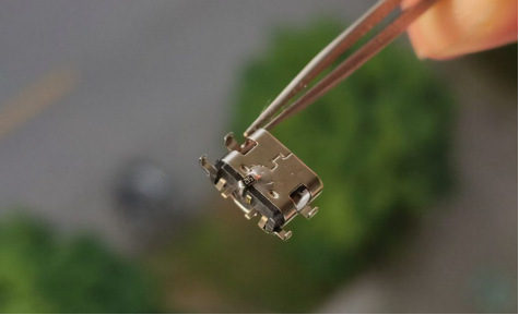
· Add the second CC pull-down resistor.
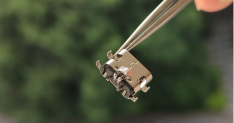
· Test the voltage using a C-to-C data cable from a PD charger.
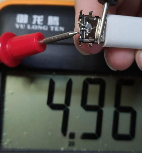
4. Working on the Charging Case:
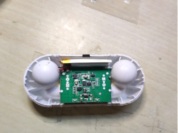
· Carefully open the charging case with a small knife, exposing the circuit board.
· For some devices, take pictures of the circuit board, disconnect the battery and cables, and remove the mainboard to prevent short circuits.
5. Replacing the Old Connector:
· Apply flux to the old female connector and build up solder.
· Use double-sided adhesive to secure the housing.
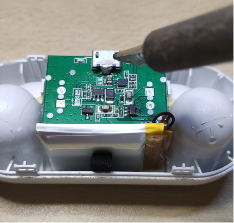
· Remove the Micro-USB female connector using the "solder pile" method.
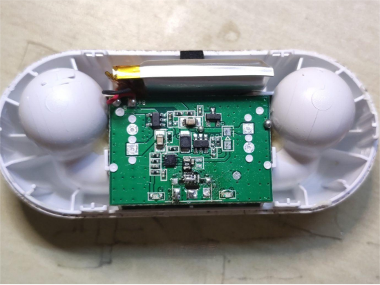
· Clean up excess solder with desoldering wick.
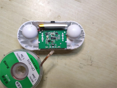
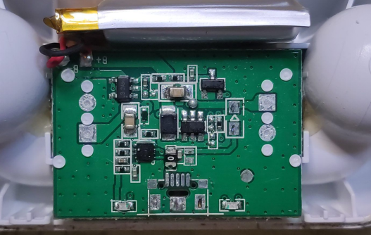
6. Wiring and Insulation:
· Connect fine wires to the ground and positive terminals.
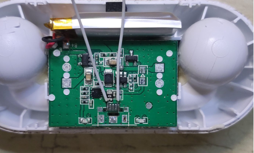
· Clean any remaining flux with alcohol and tissue.
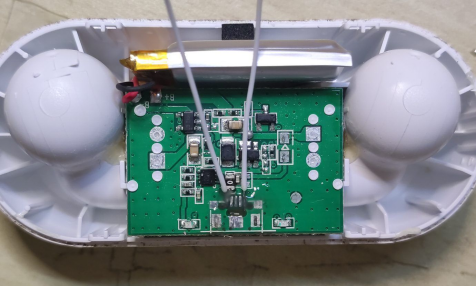
· Apply AB glue to insulate the fixed area and wait for it to cure for five minutes.
· Clean off any remaining flux with alcohol for better adhesion.
7. Fixing the New Connector:
· Apply a thick layer of AB glue to secure the connector.
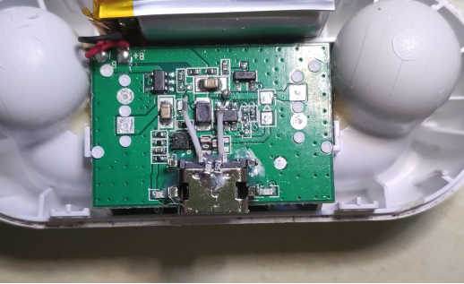
· Trim the flying wires and expose the copper strands.
· Connect the positive wire to the positive pin and the negative wire to the shell of the connector.
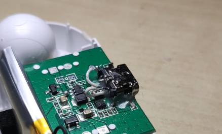
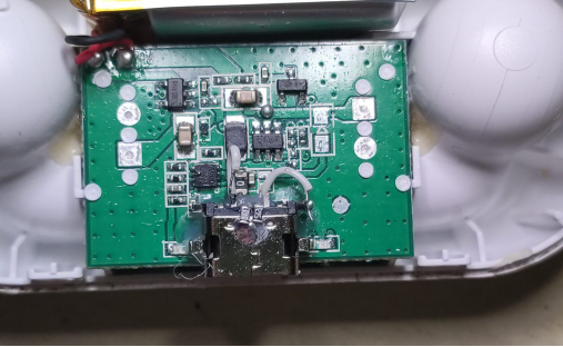
· Insert a data cable and test for power.
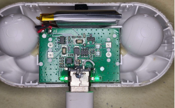
8. Final Assembly and Testing:
· Adjust the housing as necessary.
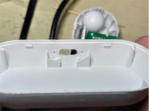
· Reassemble the device.
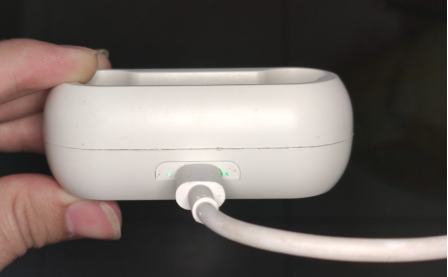
Conclusion:
In summary, this procedure offers a reliable and officially endorsed method to upgrade the power supply of Micro-USB devices to the versatile Type-C interface. This modification ensures efficient charging (up to 5V 2A) and future-proofs your device for ongoing technological advancements. For advanced features or data functions, consider alternative solutions or professional assistance. Explore this comprehensive guide for a seamless transition to Type-C compatibility.


