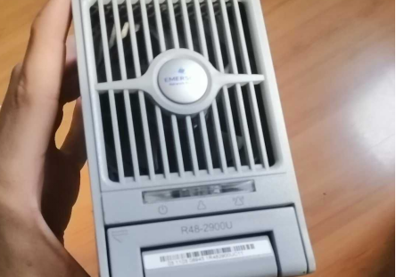
This guide provides a step-by-step walkthrough for modifying the Emerson R48-2900U power supply unit. This power supply operates at -48 volts and has a power rating of around 2900 watts with a current capacity of approximately 60 amperes. We'll explain how to adjust its voltage range and provide insights into optimizing its performance. Additionally, we'll discuss the installation of voltage and current meters and provide tips for safe and effective modifications.
Materials Needed:
1. Initial Preparations:
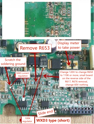
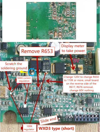
· Begin by removing the component labeled R653.
· Next, locate the copper foil near the crystal oscillator. This copper foil serves as a grounding point. You can connect it to the first leg of R650 if you prefer not to scrape it.
2. Potentiometer Installation:
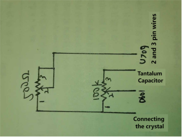
· Solder the second and third legs of the 500-ohm current-adjusting potentiometer together and run a separate wire.
· Connect the first leg of the 100k potentiometer to the first leg of the 500-ohm potentiometer and run another separate wire.
· The second and third legs of the 100k potentiometer should each have their separate wires.
· Solder the wire connecting the first leg of the 500-ohm potentiometer and the first leg of the 100k potentiometer to the previously scraped copper foil near the crystal oscillator or the first leg of the tube (this is the negative pole, and it can also serve as a connection point for voltage and current meter installation).
· Solder the wires from the second and third legs of the 500-ohm potentiometer to the second and third legs of the U709 operational amplifier. Ensure these two legs are short-circuited with solder.
· Solder the wire from the third leg of the 100k potentiometer to the end of the tantalum capacitor with a cross.
· Lastly, solder the second leg of the 100k potentiometer to the second leg of the D601 tube, which is situated near the circuit board's edge.
3. Resistor Parallel Connection:
· Parallel the 68k resistor on the surface-mount resistor R650. There is no need to distinguish between positive and negative connections. Directly solder the resistor in place.
4. Voltage and Current Meter Installation:
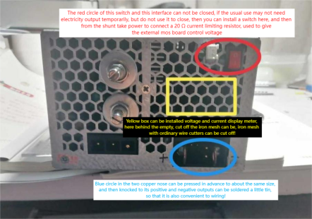
· If you have a voltage and current meter with a shunt, connect the shunt to the power supply's output and wrap it with insulating tape before placing it inside the power supply.
· If your meter does not have a built-in shunt, follow the modification instructions (also considering the wiring for power supply) as indicated in the first diagram.
· For the voltage sensing wire, solder it to the positive terminal of the output large capacitor.
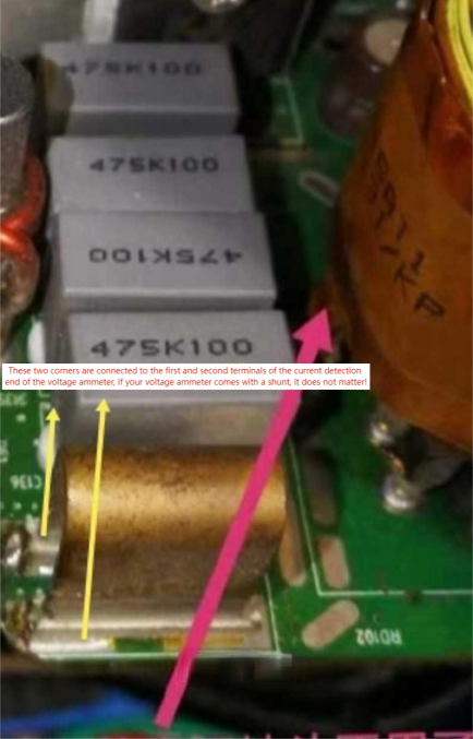
· When connecting the current meter, locate the U-shaped flat copper wire on the output side with a resistance measuring point. Solder the sampling wire on both sides of it, as shown in the fourth picture.
5. Voltage Bleed-off Resistor:
· Install the 5-watt voltage bleed-off resistor directly at both ends of the output's large filter capacitor. Ensure that the resistor value is appropriate to prevent overheating.
6. Final Assembly:
· Drill holes in the outer casing for mounting the voltage and current meters and the potentiometers. It is recommended to place the voltage and current meters on the right side of the casing and the potentiometers on the left side, making use of available space.
Conclusion:
By following these modifications, you can transform your Emerson R48-2900U power supply into a versatile adjustable power source. These enhancements offer improved flexibility and utility while maintaining the safety and performance of the unit.
Please note that these modifications should be performed with caution, and it is advisable to test the power supply before and after the changes to ensure its proper operation. The specific resistor values may vary depending on individual units, so adjustments may be required to achieve desired output voltages.
