
Discover a cutting-edge DIY solution for optimizing your solar power system's efficiency. In this article, we'll explore a custom-built control system that enables seamless management of surplus solar energy, enhancing both power usage and energy savings. Our step-by-step guide will show you how to create this system using readily available components and the Arduino platform.
Optimizing Solar Power Supply:
Are you generating more solar power than your network devices and NAS require? If so, it's possible to leverage this excess energy efficiently. With the addition of an inverter, you can repurpose surplus energy, making it available for other applications.
Fine-Tuning with Control Modules:
For precise control, a power monitoring control module with multiple control modes can be employed to manage the inverter's output. One particularly useful mode is the discharge control, which follows this logic:
· Disconnect the switch when the battery voltage falls below 65V.
· Reconnect the switch when the battery voltage reaches 66V.
This switch is connected to a dual-path relay system, enabling automatic switching between solar inverter AC220V and mains electricity AC220V.
Eliminating Standby Power Waste:
One challenge often encountered is standby power consumption after the switch is disconnected. The inverter typically draws 10-12W in standby mode, resulting in energy wastage. To address this issue, a dual-path switch can be designed to control both the inverter's output and input, eliminating idle power consumption.
The control logic for this dual-path switch is as follows:
· When turning on, connect the input first.
· After a 5-second delay, turn on the inverter's output.
· When turning off, disconnect the output first.
· After a 5-second delay, disconnect the inverter's input.
The introduction of these delays is essential due to the soft start nature of the inverter, which requires time for both startup and shutdown processes to complete without causing disruptions.
Custom Solution with Arduino:
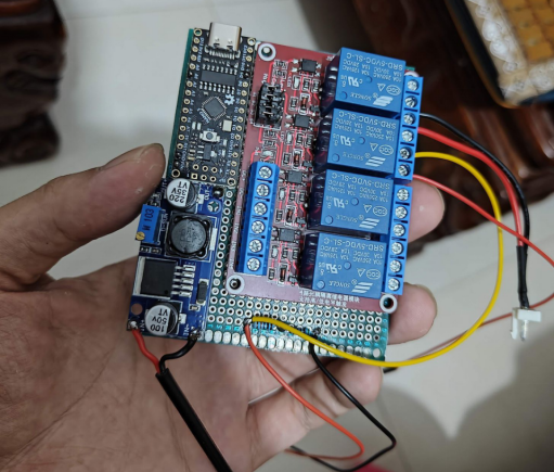
While commercial relay modules may not offer the desired functionality, we've devised a DIY solution using Arduino and a four-channel relay module. The components required for this project include:
· Arduino Nano development board
· Four-channel relay module
· LM2596S voltage reduction module
· 7*9 cm perforated board
The voltage reduction module is particularly important when a 12V dual-path uninterruptible power supply is nearby, as the 12V voltage isn't suitable to power the development board and relay module.
Safety Measures:
To safeguard your development board and ensure reliable operation, consider implementing the following protective measures:
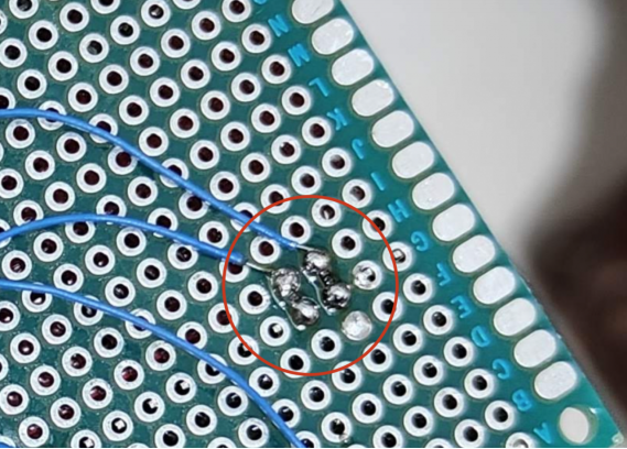
1. Introduce a 100-ohm resistor in series with two pins to control the relay's high and low levels, protecting the development board in case of relay malfunction.
2. Add 5V TVS diodes at the output of the voltage reduction module and the input of the relay module to protect against overvoltage. The TVS diode at the relay module also absorbs reverse electromotive force during relay operations.
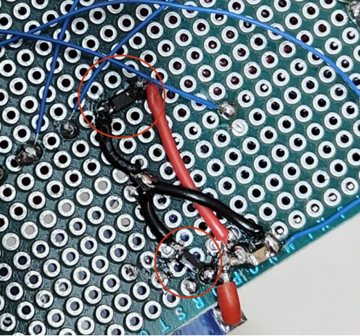
3. Include a 10uF capacitor at the input of the development board for voltage stabilization and filtering.
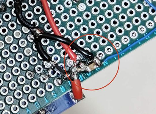
4. Insert a 1nF capacitor at the analogRead() pin to filter out high-frequency noise and prevent false triggers.
Voltage Reading and Protection:
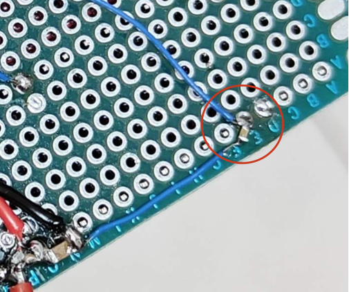
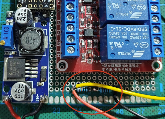
Reading external voltage values that peak at 73V can be challenging for the Arduino. A simple voltage divider circuit is employed, featuring resistors with values of 100K and 5.1K.
Handling Inverter's High-Impact Current:
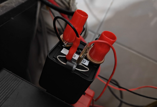
The inrush current from the inverter is too high for direct control by the relay module's small relay. To manage this, a small relay is used to control a powerful 120A relay, ensuring safe and efficient control.
Conclusion and Future Enhancements:
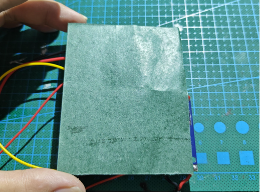
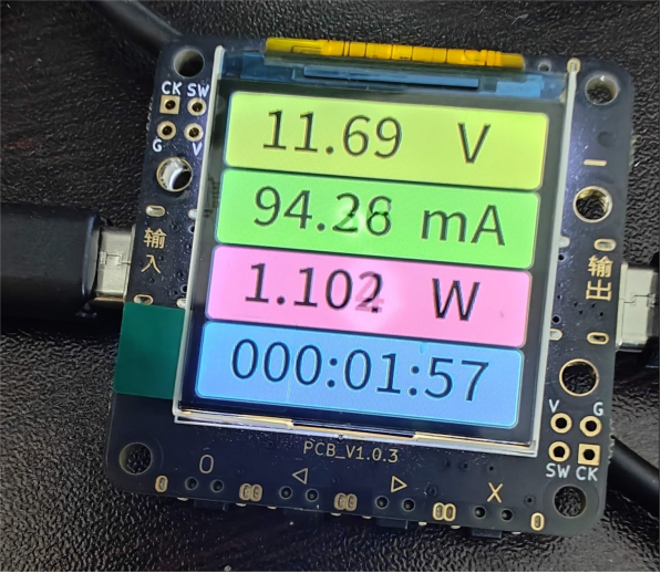
After successful assembly, ensure that you place insulating material on the back of your setup to prevent potential short circuits when placed on a metal surface. During testing, both relays exhibit an input current of approximately 0.1A, with a power consumption of around 1W.
As you embark on your DIY journey, remember the importance of incorporating diodes to protect your system. If you're eager to expand your system's functionality, consider adding buttons and a digital display, allowing for adjustable action voltage and delay duration, and paving the way for future enhancements.


