
In the pursuit of constructing a solar charging panel, one must initially focus on establishing a reliable voltage regulator. This entails the consolidation of two approximately 10-watt units using a QC synchronous buck-boost converter. While QC compatibility may not fully meet the rated power requirements, it can be harmonized with a voltage regulator to allow for the adjustment of the output voltage within a range of 4.2 to 12 volts, significantly broadening its adaptability.
Section 1: Voltage Regulation
While QC compatibility may not fully meet the rated power requirements, it can be harmonized with a voltage regulator to allow for the adjustment of the output voltage within a range of 4.2 to 12 volts, significantly broadening its adaptability.
Section 2: Panel Specifications
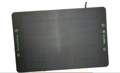
The fundamental specifications for the panel are as follows: a power output of 5 watts, an open-circuit voltage of 7.2 volts, a short-circuit current of 0.87 amperes, and operational parameters of 6 volts and 0.833 amperes.
Section 3: Component Selection
The plan involves the utilization of the IP6525T module.
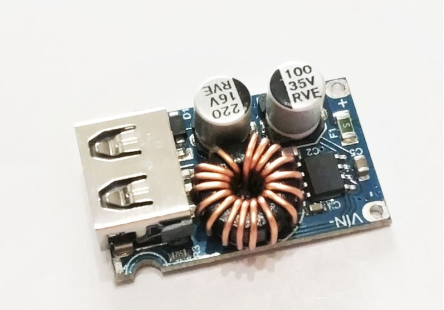
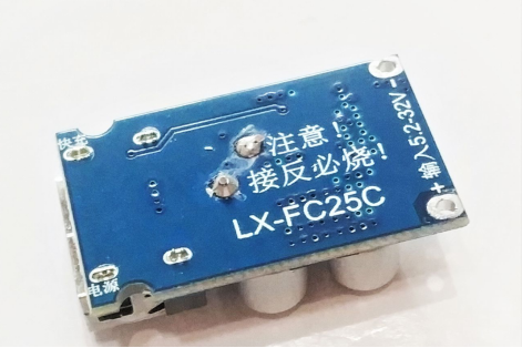
The module's suitability for a wide voltage range in QC car charging applications will be examined closely.
Section 4: Enhancing Stability
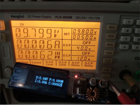
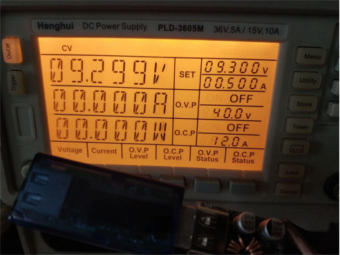
Contrary to the manual's recommendation, practical tests reveal that the module can be initiated at 9.8 volts, although undervoltage lockout occurs at 9.3 volts with a hysteresis of approximately 0.5 volts. This voltage range aligns well with the needs of the two panel sets, providing a total single-board output of around 5 volts, or roughly 10 volts for two sets. This voltage range is precisely sufficient to initiate the module. When the solar panel operates below its rated output, typically around 6 volts, the output current is severely limited in weak light conditions. If the buck-boost converter can initiate at the right voltage, it can help avoid unstable operations. Once initiated, the module functions normally when the load remains within the maximum output current of the solar panel. However, if the load becomes too heavy, it will lower the solar panel's output voltage close to the undervoltage threshold, causing a slight drop in the module's output voltage. This allows devices like smartphones to detect the voltage decrease and automatically reduce their charging current to prevent overloading the solar panel. Detailed information on various load types will be provided.
Section 5: Protective
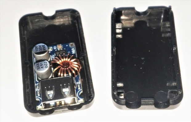
Upon finalizing the plan, the creation of a dedicated enclosure will be the next step.
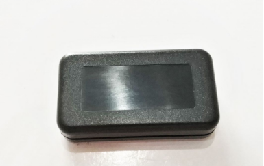
The enclosure will feature two holes on one side and a single hole on the other side, accommodating U-shaped connectors.
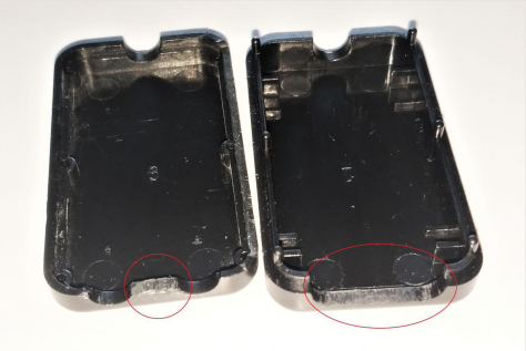
A key aspect of this process involves meticulously smoothing the red-circled areas.
Any gaps around the board will be sealed using black plastic and a hot-melt adhesive, ensuring a seamless finish.
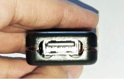
Following the successful completion of the voltage regulator, the focus will shift towards optimizing the solar panel. This will include addressing the remaining soldering requirements for the backside pins.
A basic test under overcast conditions has revealed an open-circuit voltage of 6.3 volts and a short-circuit current of just 23 milliamperes. It has become evident that this particular panel may not perform effectively in cloudy conditions, a common limitation of monocrystalline panels in such scenarios. Testing under direct sunlight has yielded an open-circuit voltage of around 7 volts, with a short-circuit current of approximately 440 milliamperes. Given the testing conditions, the operational current will likely be lower, resulting in an actual power output of approximately 2.5 watts, roughly half of the panel's rated capacity.
Section 6: Voltage Regulator
If issues arise with the other panel, it may necessitate a shift to a single-panel configuration.
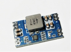
This, in turn, would prompt the adjustment of the buck-boost scheme. For this purpose, the Mini560 module with a maximum 5-ampere output and a versatile input range spanning from 4 to 23 volts could be employed.
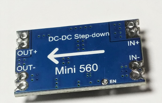
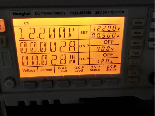
Empirical testing has indicated a low-voltage shutdown threshold of 3 volts, with a static current of merely 2 milliamperes at 5 volts output and a voltage drop of less than 0.2 volts at 1 ampere output. This impressive performance aligns well with the voltage regulation requirements, as it incurs minimal power loss even under the strain of output currents approaching several hundred milliamperes.
Section 7: Heat Dissipation
To enhance the setup's stability and performance, a compact casing has been designed, and strategic modifications have been implemented to optimize heat dissipation. The addition of a U-shaped connector on the right side and the application of thermal silicone pads at the base, although unnecessary due to minimal heat generation, were introduced to enhance heat dissipation.
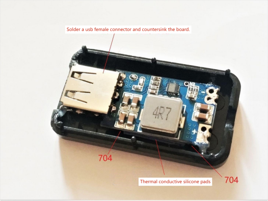
An input cable was integrated on the left side, and UV glue was utilized to secure the board around its periphery.
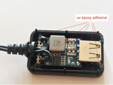
The resulting assembly exhibits a flawless fit and finish.
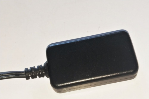
Section 8: Completed Setup
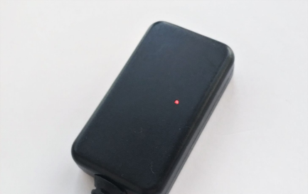
When subjected to direct sunlight, the assembly's red light indicator is triggered. Notably, this light is a clear signal of the assembly's successful operation under ideal conditions.
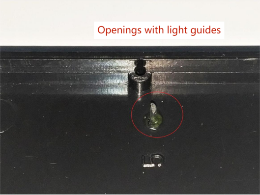
Section 9: Testing and Efficiency
With the voltage regulator incorporated and effective sunlight penetration achieved, the assembly's open-circuit voltage in direct sunlight is examined.
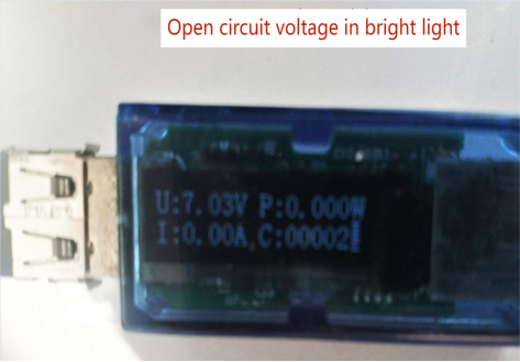
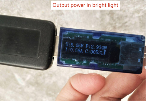
Upon engaging the voltage regulator, configured with an open-circuit voltage setting of 5.06 volts, it's possible to achieve a maximum output of approximately 3 watts when charging an IP5306 power bank under strong sunlight. This translates to a peak current of 580 milliamperes at the battery's input terminal. Extensive testing has demonstrated that, under such conditions, it takes roughly four hours to recharge a 3000mAh power bank to full capacity.
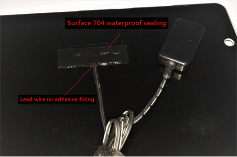
In order to facilitate ease of storage, self-adhesive tape is applied. Once the connections on the board's reverse side are soldered and secured with UV glue, a coating of black 704 sealant is administered to ensure water resistance.
Conclusion:
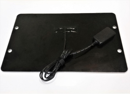
The finished product is well-suited for charging smartphones, power banks, and various 5-volt devices, presenting a power output of around 3 watts under direct sunlight. While this capacity may appear modest, it's a commendable accomplishment considering the compact dimensions of the single panel.
By following these steps and taking a systematic approach to building your solar charging panel, you can harness the sun's energy efficiently and effectively power your devices, even in challenging conditions.


