Let's delve into the research on communication modules for shared bicycles.
To begin, it's important to distinguish that this module is labeled as 800C, which differs from the SIM800C's 800C, as the two have distinct cores. This module is powered by the MT2503DV, an Internet of Things chip platform based on ARMv7 with high integration, offering support for high-precision global satellite navigation (GNSS), Bluetooth 3.0, and 2G baseband capabilities. It is particularly suited for applications in simple mobile devices, security, and industrial settings. In contrast, the SIM800C is built around the MT6261MA core. Notably, SIMCom's product line also includes the SIM868, which shares the MT2503DV core, allowing for firmware flashing.
The rationale behind firmware flashing is straightforward. This module doesn't require additional microcontroller drivers, and it's highly probable that the code for controlling the unlocking process resides within the module itself.
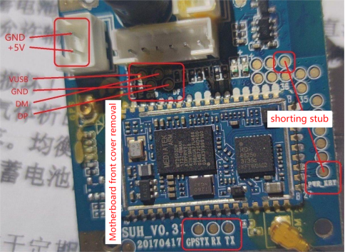
The accompanying diagram provides a visual representation of the connections, and it's recommended to remove all the white sockets for optimal clarity.

Notably, this board features two power interfaces, one of which is positioned at the top of the image and shares the same wiring configuration as the left one. Removing the white sockets facilitates better visibility of the silk screen.
It's worth mentioning that yellow glue, while effective, can be a bit challenging to manage due to its broad coverage, high elasticity, and stubborn adhesive properties. It can be carefully removed by using a cleaning solution.
Here's a systematic guide for flashing the firmware:
1. Begin by inserting and properly configuring the USB to serial module, making a note of the corresponding port number.
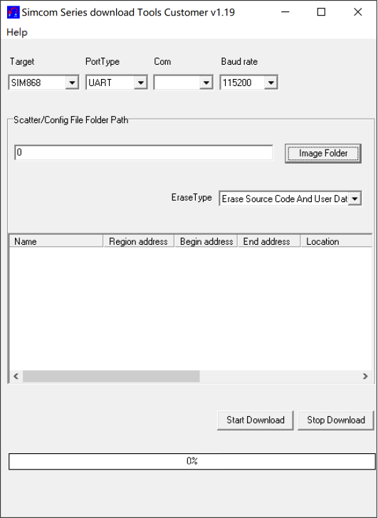
2. Open the software by running the "Flash_tool.exe" file. If a dialog box containing "Scatter" appears, simply click "OK." This indicates that the firmware configuration file wasn't found.
3. Configure each parameter as shown in the diagram (select the appropriate port under "Com"), and then click "Image Folder" to load the firmware.

4. Follow the wiring instructions as per the diagram but refrain from powering up the communication module at this stage. Remove the SIM card, select all the names in the list, and click "Start Download." When the progress bar reaches "0% (Waiting)," power up the module. At this point, the power requirement is minimal, and you can power it directly using the USB to serial module. The download process will begin automatically; if not, attempt the operation multiple times.
5. Exercise patience for a few minutes (avoid abrupt power disruptions during this period). When a dialog box with a green circle and download time is displayed, it signifies a successful flashing.
6. Close the software, disconnect the power to the communication module, and insert the SIM card.
Following the firmware flashing, it's necessary to remove the power connection between the USB to serial module and the communication module. Then, procure a power source capable of delivering at least 5V 2A. Connect it to the "BAT" terminal, as indicated by the silk screen, for adequate power, and follow the wiring instructions on the diagram. Ensure that the PWR_KEY is grounded (neglecting this step may lead to automatic shutdown). Finally, ensure that the USB to serial module and the communication module share a common ground. After verifying the absence of wiring errors, proceed to power up the module.
Upon powering up, launch a serial port debugging tool, select a baud rate of 9600, and initiate the serial port. Send the command "AT↓" (↓ denotes a line break). In normal conditions, you should receive an "AT↓OK" response, enabling you to utilize the AT command set for module control, with reference to the SIM868 documentation.
It's worth noting several known issues:
1. Weak signal strength may be attributable to antenna limitations, particularly the standard printed antenna's performance.
2. When employing a mobile 4G USIM card, issues related to authentication rejection during network registration have been observed. The underlying cause of this problem remains elusive, preventing subsequent operations and obscuring registration status codes.
3. Bluetooth signals are transmitted by an independent chip, BK3431S, and the precise logical connection between Bluetooth and MT2503DV remains undetermined. Consequently, the Bluetooth functionality remains unutilized.
4. A lack of module-related information presents challenges in understanding the definitions of various test points.
A helpful reminder: If your SIM card is locked, initiate the "AT+CPIN=yourPIN↓" command to unlock it.
After successful firmware flashing, you can embark on development using Embedded AT.


