
The LM399, a precision voltage reference manufactured by Analog Devices (ADI), is renowned for its ultra-low temperature drift, making it ideal for applications demanding high stability. This guide outlines the circuit design, construction, and testing procedures for a customized LM399-based voltage reference, suitable for use in precision measurement instruments such as 6.5-digit multimeters.

Circuit Design:
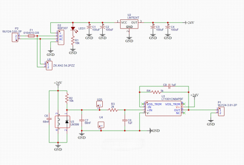
According to the data, the LM399 operates within a voltage range of 9-40V. The constant temperature circuit has a maximum operating current of 600mA. The internal Zener voltage regulator has a minimum stable current of 1mA. Considering a 24V AC output transformer, rectifying to approximately 35V DC, an LM7824 regulator reduces it to 24V. A 10k resistor is used to limit the current through the internal Zener regulator. At this point, the internal Zener regulator operates at a current of 2.4mA, exceeding the minimum required 1mA. The LM7824 exhibits a voltage drop of 11V at its maximum 600mA current, resulting in a power consumption of around 6.6W. Despite the seemingly high power consumption, the constant temperature circuit's maximum current lasts only a few seconds. After temperature stabilization, the current drops to just over 100mA. With a heat sink in place, this poses no issues.
The circuit, following a slight modification based on the application circuit on the fifth page of the manual, omits the voltage divider and trim resistor since the LM399's minimum temperature drift is only 0.3PPM, making it challenging to find resistors with a similarly low drift.
The modified circuit involves rectifying and filtering the AC voltage before supplying it to the LM7824 for regulation and filtering. The output is then connected to both the LM399 and LT1001. Both the input and output of the LM399 and LT1001 have 68nF CBB capacitors for filtering. The LT1001's input employs an RC circuit for additional filtering, and a feedback loop with resistors and capacitors ensures a more stable output.

PCB Layout:
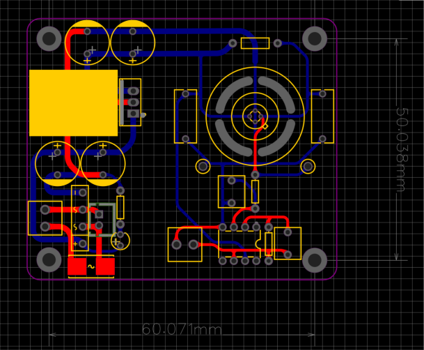
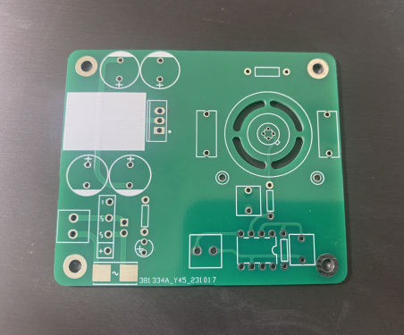
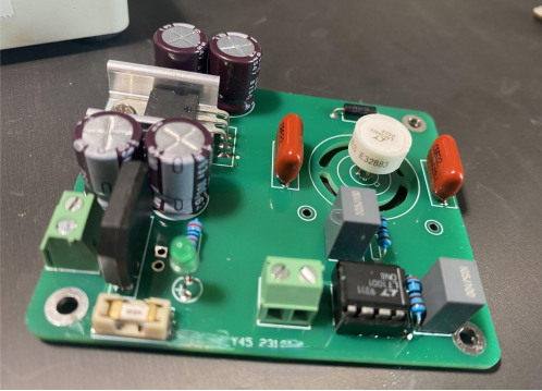
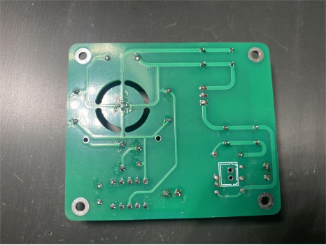
The 3D simulation of the PCB is shown below:


Power-on Testing:
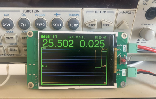
Using an adjustable power supply, set the output voltage to 24V and the output current to 100mA to prevent any circuit issues leading to component damage. Upon opening the output, observe the current curve on the voltmeter.
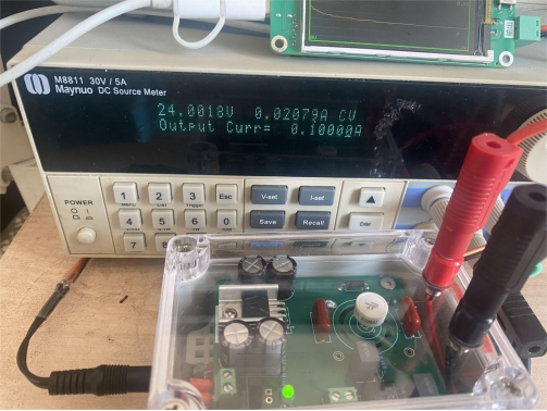
The current stabilizes around 22mA after some time, indicating normal circuit operation.

Set the adjustable power supply output to 25.2V, open the output, and observe if different input voltages affect the LM399's output.
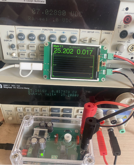
Use the voltmeter to observe startup voltage and current. During startup, the voltage drops to 12V, with the current limited to 100mA.
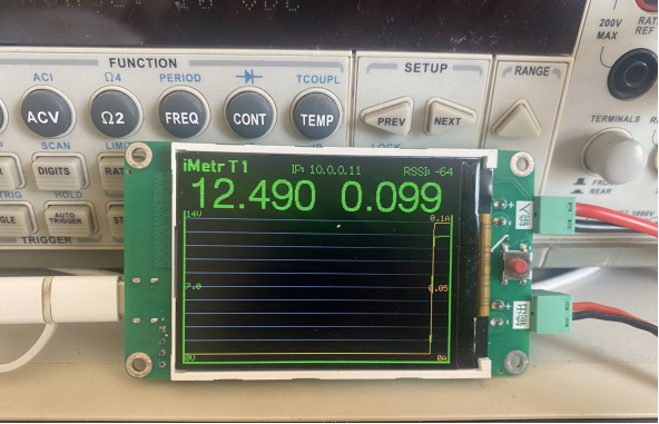
After startup, the voltage returns to the set output voltage, and the current rapidly decreases. The yellow line represents the current, stabilizing at around 18mA.
Stability Testing:
Connect the LM399 to a thoroughly heated 6.5-digit multimeter, use software to record voltage values, and observe the stability of the LM399 output. Although there is some voltage fluctuation, it remains generally unchanged, aligning with the LM399's characteristic of high output noise.

Conclusion:
In conclusion, the LM399-based voltage reference, designed and tested as per the outlined procedures, meets stringent stability requirements. Its application in verifying the accuracy of 6.5-digit multimeters is validated through extensive testing. Users can confidently integrate this LM399 reference into their measurement setups for consistent and reliable performance.


