
In this guide, we explore the development of a compact DC-DC board as a substitute for the commonly used 7805.
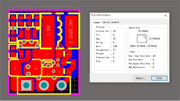
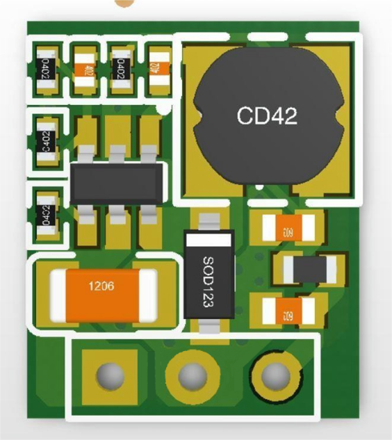
The accompanying PCB layout showcases a remarkably diminutive form factor, and the three-dimensional rendering provides a visual perspective of the design.
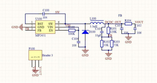
Schematic Overview:
The schematic simplicity is a key feature. When employing the mp2451 chip in conjunction with a Schottky diode (SOD123 package), consider the B5819W diode (marked as SL) with a 40V 1A capacity. Alternatively, for the mp2459, a diode with a 60V voltage rating is necessary.
Inductor Selection:
For the inductor, a judicious choice is a 120-ohm variant with a DC current rating of approximately 1A. The TDK MPZ series, exemplified by the MPZ1608S121, is a fitting candidate for consideration.
Input Capacitors:
Given the requirement for a 50V voltage rating, the 1206 package for the input Multi-Layer Ceramic Capacitor (MLCC) is recommended.
Board Comparison:
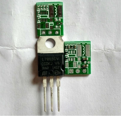
Notably, a visual comparison with the traditional 7805 reveals a compactness surpassing even the TO-220 package.
Front and Back Overview:
One board showcases a 0402 resistor and capacitor, while the other board, albeit devoid of components, exhibits precise soldering.
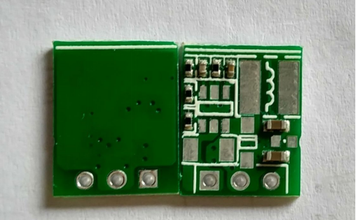
Chip and Inductor Examination:
The selected DC-DC chip is the mp2451, accompanied by a 3.3uH inductor. However, a reevaluation of the 2A current capacity is suggested.
Soldering Results:
The soldering results, with the mp2459 on the left and mp2451 on the right, underscore the practical aspects of the design.
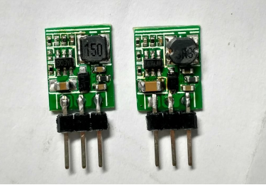
Performance Testing:
Detailed testing of the mp2451 reveals stability up to 12V, with an operational range comparable to the 7805.
Due to not achieving 100% duty cycle, 5V input is the maximum.
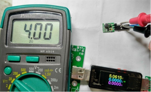
6.4V is insufficient.
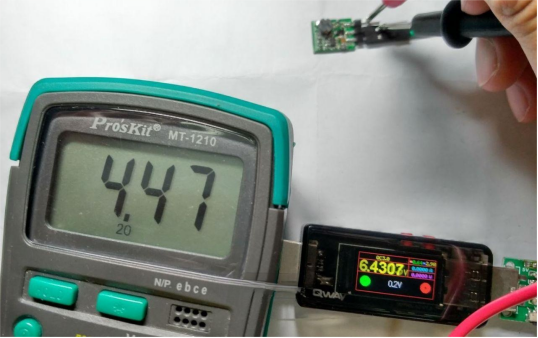
Stable output at 7.2V.
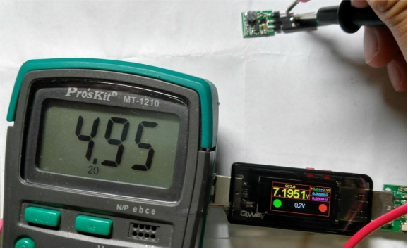
Stable until 12V, further testing wasn't conducted. The chip works well up to around 24V, similar to the 7805 in terms of input voltage range.
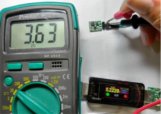
Testing the mp2459 shows similar results.
Technical Data:
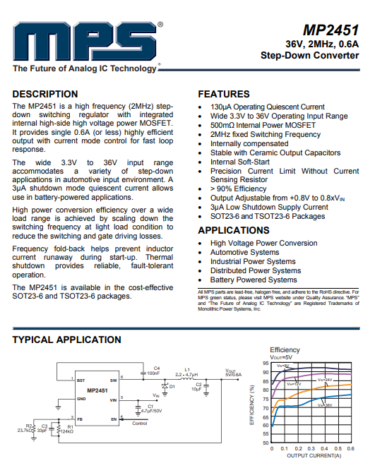
The mp2451 boasts a voltage tolerance of 36V, though exceeding 30+V is cautioned against. The recommended current is 600mA.
Optimal Dynamic Performance:
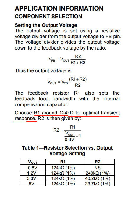
Enhancing dynamic performance involves a voltage divider upper arm resistor of approximately 124k, pragmatically adjusted to 120k for convenience. The lower arm employs 33K and 75K resistors in parallel.
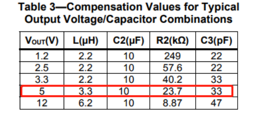
Component Considerations for mp2459:
With a higher voltage tolerance up to 55V, the mp2459 accommodates inputs up to 48V. The necessity of a higher voltage difference for smooth operation is emphasized.
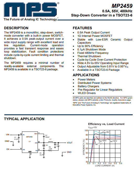
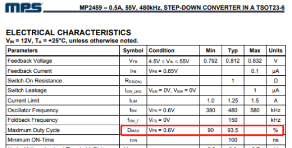
Component Selection:
For the mp2459, an inductor between 10-22uH is suggested, with 15uH chosen for this application. The voltage divider and compensation capacitor mirror those of the mp2451.
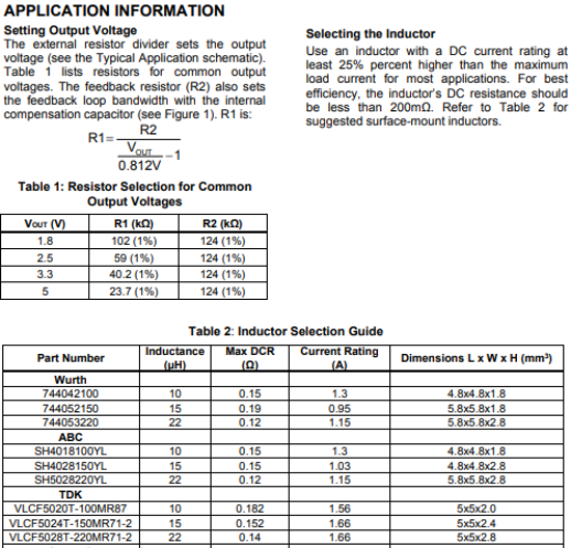
Efficiency Enhancement:
Consideration is given to efficiency improvement by incorporating a diode for bootstrap capacitor power supply when outputting 5V.

Conclusion:
The versatility of the chip's package, featuring numerous compatible substitutes, warrants a meticulous review of the manual for precise component selection. This comprehensive guide is designed to facilitate both understanding and implementation in the development of an efficient and compact DC-DC board.


