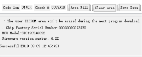
When writing code, the process of repeatedly modifying, downloading, verifying, and then modifying again is inevitable. If you don't want to generate the HEX file and manually press the reset button on the development board, you can try creating an automatic download device.
The CH340 implements USB to TTL, using an 8-pin 15F104W microcontroller to monitor the 0x7f signal of the download software handshake. Then it turns off and on the power of the target microcontroller, completing the automatic power-up download. To accommodate both 3.3V and 5V levels, a switching circuit is designed. This way, when working with 3.3V devices like ESP8266, it feels more reliable, and it can also handle direct 5V connections without the risk of burning out. If you've done automatic downloads before but encountered issues with incomplete disconnection due to voltage on TX and RX, you can try cutting off the GND of the development board this time.
Schematic:
Three MOSFETs are used to switch the power supply and V3 pin of the CH340. Two LEDs indicate whether it's handling 3.3V or 5V levels, and another LED reflects the power status.

PCB


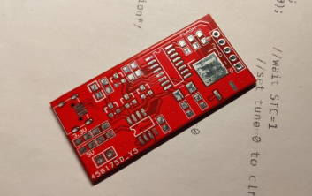
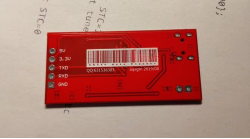
Carefully arrange the components, and a quick blast from a hot air gun should suffice. If the solder paste is unevenly applied, the results may not be optimal, but you can touch up with additional soldering.

After thorough checks, if the computer still doesn't recognize the device when plugged in, it could be due to the following reasons:
· MOSFET's D and S are reversed. Reversing the MOSFET should resolve the issue.
· After pressing the download button, if the computer makes a sound and the CH340 disconnects, adding a 47uF capacitor can solve this.
· When outputting 3.3V at 5V levels, if the voltage is abnormal, it might be due to 5V backflowing into the 3.3V pin through the MOSFET's internal diode. Adding an SS14 diode for isolation should normalize this.

If the jumper wires seem fragile, applying some glue can help.

Red for 5V, green for 3.3V.
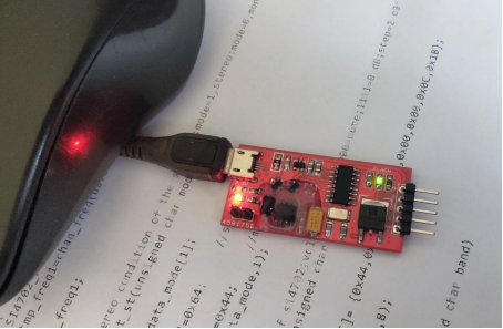
Connect to the experimental board.
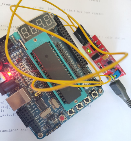
Successful recognition.
![]()
Check the option below, and it will automatically download when the file changes.

Ready to use.
