
For individuals frequently on the move, checking the time on a mobile device necessitates unlocking it, resulting in potential inconveniences. A viable solution lies in the creation of a straightforward, portable clock. The hardware in question is designed to function on a 3-6V direct current power supply.
Assembly Instructions:
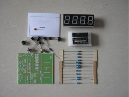
Initiate the assembly process by soldering the resistors onto the electronic clock circuit board.
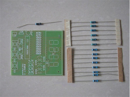
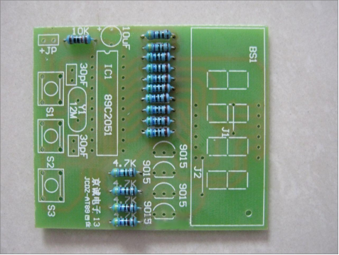
Once the resistors are securely in place, proceed to solder the chip socket, buttons, and crystal oscillator.
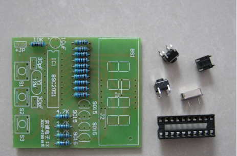
Solder the capacitors and transistors in accordance with the provided guidelines.
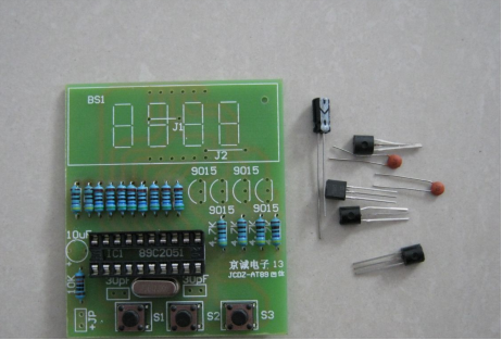
Proceed to solder the digital display onto the circuit board.
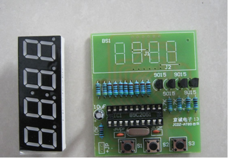
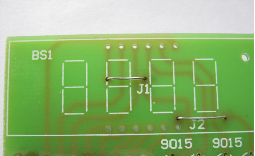
Beneath the digital display, identify and solder the two essential jumper wires.
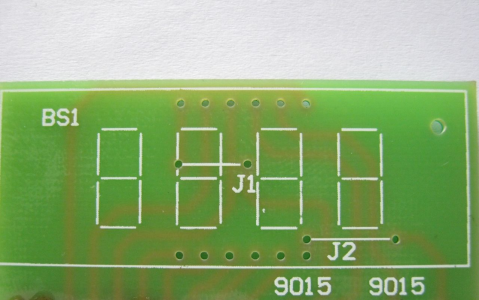
Establish proper connections for the jumper wires.
Facilitate testing by inserting the AT89C2051 microcontroller into its designated socket; note that the program has already been programmed onto the chip.
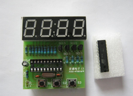
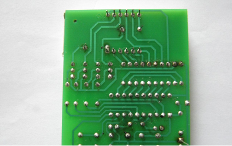
The circuit board's backside should remain devoid of any connections.
Power up the device; upon successful activation, the digital display should illuminate. S1 serves as the reset button, S2 as the function button, and S3 as the set button. Consider omitting S1 if deemed unnecessary.
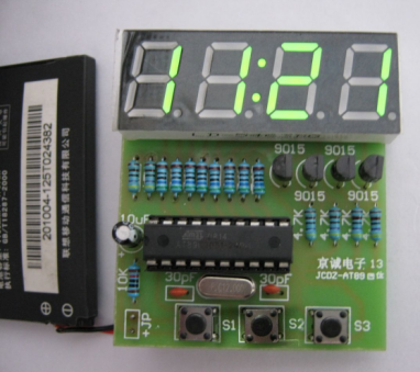
This portable clock solution offers a convenient and efficient time-checking alternative for those frequently on the go.


