
Discover an effective method for converting motion sensor lights to lithium battery power while preserving their original aesthetics and structure. This comprehensive guide outlines a streamlined process with minimal alterations, ensuring easy restoration and efficient power usage.
Key Points:
1. Motion Sensor Light Features:
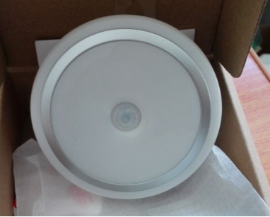
The light comes with both motion and light sensors, and the motion sensor covers just the right range. The battery setup consists of three batteries arranged in a row, making it easy to modify. Another option is a triangular arrangement of three batteries.
2. Exterior Structure:
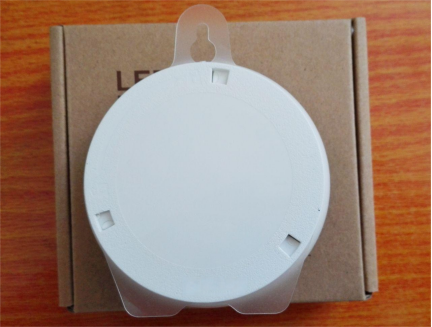
On the backside, a rigid plastic layer is sandwiched between the battery cover and the light body. It serves the dual purpose of providing a hanging point on top and acting as a stand at the bottom, allowing the light to stand on a flat surface. This plastic layer greatly facilitates the modification process.
Battery compartment:
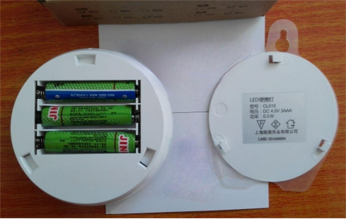
The internal space is quite spacious. Upon disassembly, the decorative ring proved tight, but with a careful approach, it was possible to dismantle it without leaving any traces.
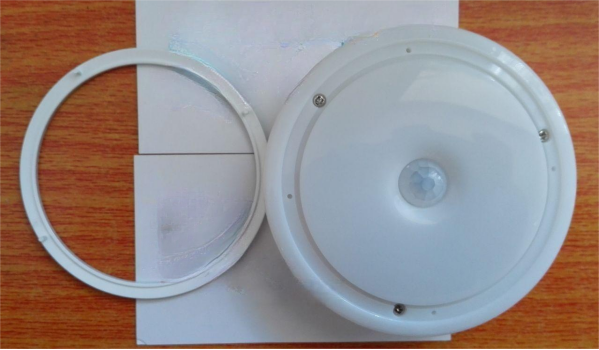
Removing three screws and zooming in:
3. Disassembly Process:
Disassembling an old POS card reader:

De-soldering the IC card slot:
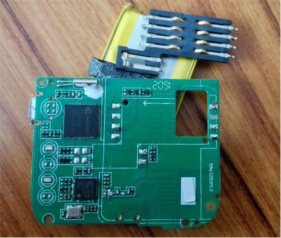
On the other side of the circuit board, removing the magnetic head, with the card swipe head on the right.

4. Circuit Board Optimization:
Disconnecting unnecessary parts of the circuit, retaining only the charging section to minimize power consumption.
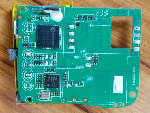
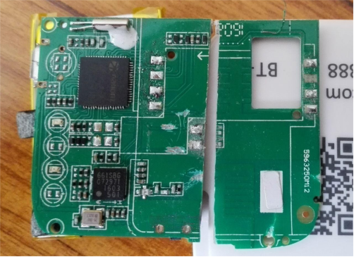
Unnecessary sections are cut to reduce volume for backup.
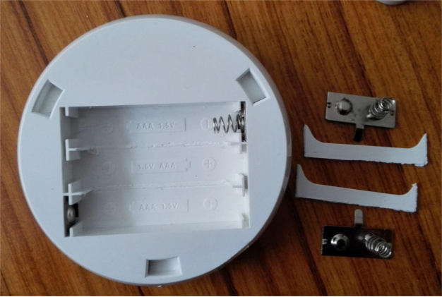
5. Battery Compartment Enhancement:
Removing the middle partition of the battery, a slight modification that allows the use of batteries in the future.
6. Plastic Layer Modification:
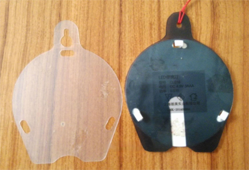
The transparent part on the left is the original, while the black part on the right is cut from an X-ray film. It includes the location for the switch, IC card slot switch, cut and shaped from corner scraps.

7. Switch Box Innovation:
The backside of the switch box is made by folding a narrow strip cut from an X-ray film.
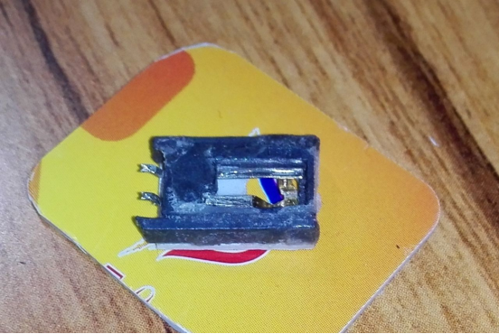
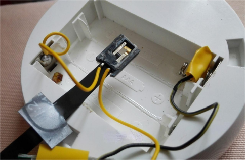
A transparent board serves as a circuit board cover to prevent short circuits.
Connecting the switch to the positive pole of the power supply. The black strip is the switch pull bar made from an X-ray film, which works smoothly for both turning on and rebounding.
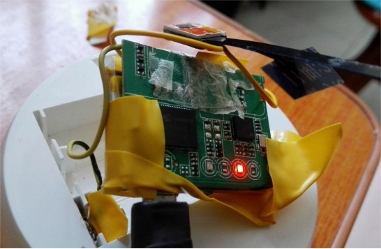
Placing the assembled circuit board and testing it with a power plug:
8. Testing and Final Assembly:
Checking the installation position of the switch pull bar, ensuring it fits snugly against the battery compartment edge.
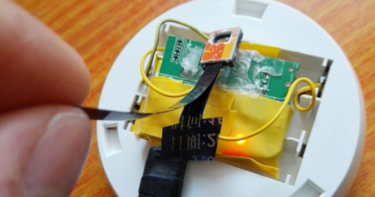
Using double-sided tape to secure the switch box in place.
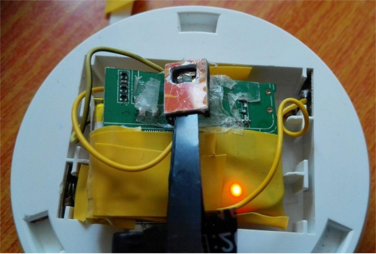
The final look, with the charging indicator covered by tape.
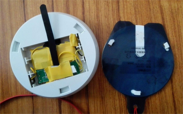
A small hole is made to remove unnecessary tape.
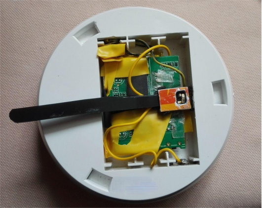
Closing the battery cover, pulling out the switch bar turns off the light completely, while pushing it in turns it on.
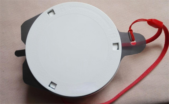
The light operates with both light and motion sensors when in use.
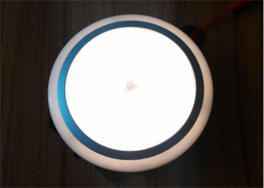
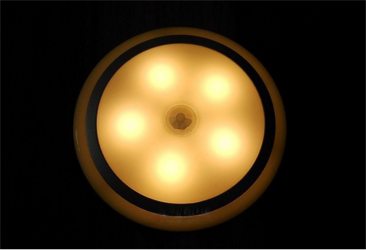
Conclusion:
This detailed guide offers a step-by-step approach to transforming motion sensor lights into a more energy-efficient and versatile configuration. With an emphasis on preserving aesthetics and functionality, this modification ensures optimal performance while reducing power consumption. Explore the possibilities of enhancing your lighting solutions with this innovative and accessible conversion process.


