The goal of this firmware is to achieve highly customizable control of keyboards and mice. This controller can convert common built-in laptop keyboards and trackpoints into USB interfaces while also replacing the controller of existing keyboards.
For example, it can simulate a mouse using the keyboard, create multiple layers of virtual keyboards, and importantly, the matrix can be flexibly entered through virtual serial ports.
Let's DIY a more powerful and user-friendly multifunctional universal keyboard and mouse controller firmware together.
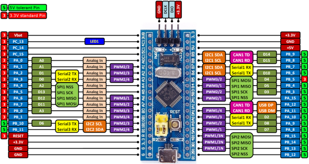
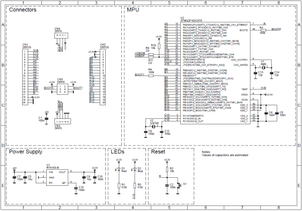
The hardware used is a small board, and detailed diagrams and schematics are provided here.


Below is the scanning firmware that solves the grouping and mapping of matrix rows and columns, capable of scanning any number of rows and columns up to 30 in the key matrix.
Universal Matrix Scanning Firmware
[0...29], a total of 30 pins corresponding to the content of kb_scan_pins.txt, note that the USB PA11 PA12 is not used. For easy wiring, the order of the small board is directly used.
Flash the firmware scanner.bin. Connect to the computer via USB, and you'll discover a new device: a serial port, a keyboard, and a mouse. The serial port driver has only one file, kbcfg_acm.inf, and it should install without signing.
Test the firmware. Open a software like Putty, connect to the serial port, and press the cap lock key on the original keyboard. You should see output information on the serial port. Press Ctrl and arrow keys simultaneously in the Putty interface, and you should see the mouse move.
Connect the keyboard to be scanned. Remove the development board, connect the 30 pins to the keyboard's ribbon cable, and it's okay if you don't use them all. Start from 0 if possible for easier correspondence between the cable sequence and the firmware print sequence.
Generate the matrix and key mapping list. Connect the small board to the computer and wait for the device to load. Open a text editor, write ESC with the original keyboard, press tab, and then press the Esc key on the connected keyboard. Two numbers will appear, representing the row and column corresponding to the Esc key's ribbon cable. Record the row and column numbers for all keys in order.
The resulting file might look like this:
ESC 1 23
F1 2 6
F2 11 17
...
With this file, it's easy to generate a two-dimensional matrix. The crucial part is dividing the ribbon cables into rows and columns, which used to be a hassle with a multimeter but is now easily done on a computer with Excel.
This firmware can be used to solve keyboard modifications or similar situations, but note that the key matrix should not carry electricity.
Once the rows and columns are sorted, soldering is all that's left, and you don't need to worry about the order. In the future, this firmware will add the functionality to dynamically load matrices into ROM via virtual serial ports. This way, hardware-related tasks can be adjusted through software, making expansion quite easy.
Note that this firmware is suitable for hardware with fixed USB pull-up resistors and an 8MHz crystal oscillator.


