The modified Unifying™ mechanical keyboards this time are all 104 keys. The main controllers used are K260, K270, and K520. Since Logitech's K240 and similar shortcut keys are located on F1-F12, keycaps with these characters are not readily available in the market. Using them is not very convenient. Additionally, the position of the Unifying main control board in the 87-key mechanical keyboard is relatively tight.
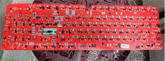
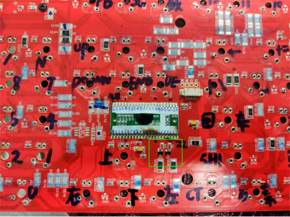
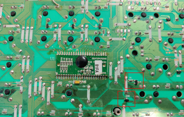
Currently, the main focus of the modified mechanical keyboards is the FL·ESPORTS GT104. This keyboard mainly has two types of mainboards and two types of positioning steel plates. Let's start with the two mainboards. The appearance of the main controllers is the same, but one type of main controller only lights up when connected to the computer, like the red board in the picture. For this type, modification is needed at the triode outputting control light on the main control pin. The modification involves desoldering the triode and replacing it with a diode or directly short-circuiting the other two pins, or connecting a dual diode to the original matrix position.
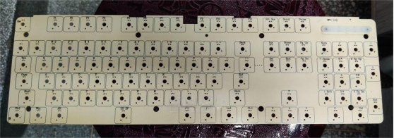
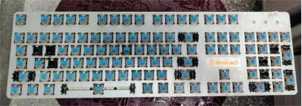
The two types of positioning steel plates are one where only FL·ESPORTS' balance bar for the space key can be used, and the other, shown in the picture, is a positioning steel plate compatible with keycaps available in the market. When modifying, pay attention to choosing a compatible option.
To ensure the lights function normally during modification, the original circuit related to the lights on the main board must not be damaged. The red main board has an advantage—it is a single-sided board, and all the cross-joint parts are 0-ohm surface-mounted resistors (SMDs) on the front side, so the back side can be ignored. However, some of the 0-ohm resistors are responsible for the circuit related to the lights and need to be retained. Anything related to the axis should be desoldered, including dual diodes. Then, reconnect the wires according to the new main control matrix.
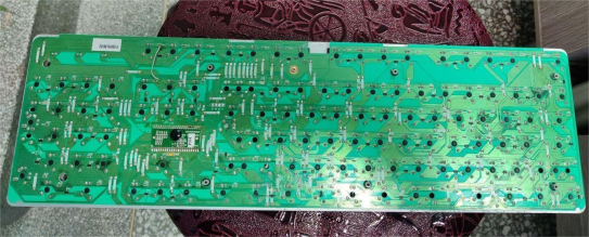
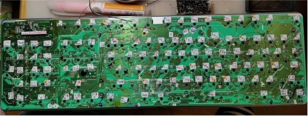
The green main board also has an advantage—the circuit related to the lights does not need to be touched. The back has wires for cross-joints related to the axis, and they need to be removed with a soldering iron. This is more complicated.
For the jumper wire, use the secondary of a 2-3W transformer, about 0.4mm. Connect it to the nearest key from the Unifying main control using multi-stranded copper enameled wire from headphone cables because the 0.4mm wire is too stiff and might break or strip off the copper foil when folded in the dense pin area of the main control board.
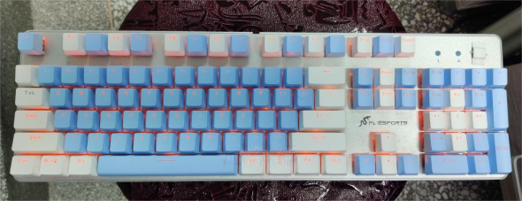
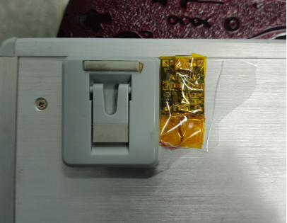
For the battery, find a 4-500mAh battery from a children's watch and place it inside. Then, use a 4056 charging board, connect the battery to two 4148 diodes, and then connect it to the Unifying main control. The lights are directly connected to the battery. If you don't want to find a place for the charging board, you can place it next to the back foot support and attach it with foam tape. You can check the finished product below.
