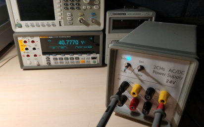
If you are seeking to assess the capabilities of your current headphone amplifier power supply, but find the conventional methods of organizing transformers and terminal arrangements unappealing, consider crafting a sophisticated desktop power supply unit for enhanced aesthetic appeal.
Initiate the process by completing the schematic diagram.
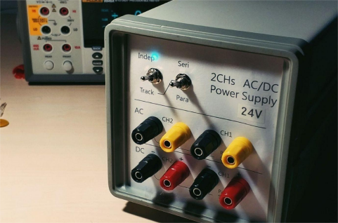
The finalized version of this power supply boasts a rich feature set, featuring two independent AC outputs, two distinct rectified outputs, and an innovative "tracking" functionality. This allows for the configuration of both channels in series or parallel through a convenient panel-mounted toggle switch, enabling a doubling of voltage or current output. This design caters to applications requiring high voltage or current, streamlining complex wiring operations, ensuring a clutter-free desktop, and optimizing overall efficiency. Notably, this design principle is prevalent in various two-channel power supply products, including those from reputable brands like GW Instek's GPD series.
Essential materials for constructing this power supply include terminal blocks, custom front and back aluminum panels, and tailor-made circuit boards - all of which are cost-effective. Additionally, readily available inventory items such as the main transformer, dual 20V 100VA, auxiliary small transformer, relay, rectifier bridge, switch, power socket, etc., can be utilized to avoid unnecessary expenditures.
Technical Specifications:
· Independent Mode:
AC Dual Channels - Transformer Direct Output, Approximately 20V, 2.5A per Channel
DC Dual Channels - Rectified Direct Output, Unfiltered and Unregulated
· Series Tracking:
Output - 40V, 2.5A
· Parallel Tracking:
Output - 20V, 5A
The circuit's complexity is minimal. In independent mode, it employs bridge rectification, while relay switching is deployed exclusively in tracking mode to connect various secondary coils. Initiate the construction process by drafting a schematic using AD.
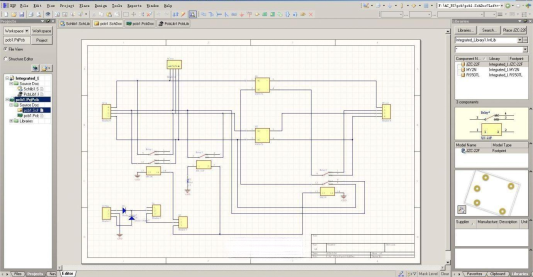
The main transformer features dual independent windings to facilitate AC series, parallel, and tracking functionalities. The auxiliary transformer, sourced from a dual 13V center-tapped unit, is rectified to power the DC12V relay. Assembling for parallel tracking is straightforward, requiring a two-contact relay to connect the two secondary coils of the transformer in parallel. For series tracking, the design emulates commercially available products, incorporating a switching terminal to connect the positive terminal of Ch1 and the negative terminal of Ch2 for series voltage output. This necessitates a three-contact relay, or two relays connected in parallel if the former is unavailable.
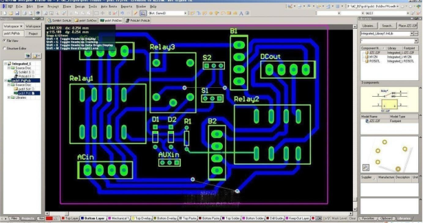
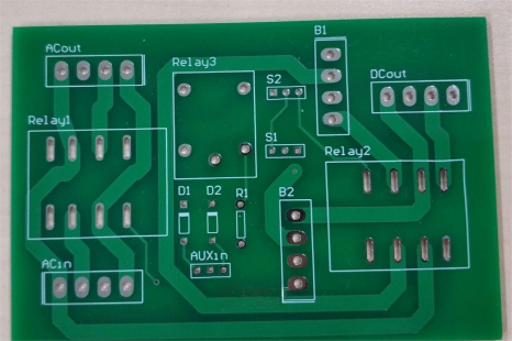
For the single-sided board, considering space constraints within the casing, the inclusion of jumpers is inevitable. The power line circuit employs a 3mm line width, and the control line circuit adopts a 1mm line width, eliminating the need for jumpers with a double-sided board.
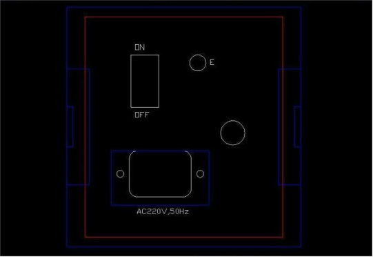
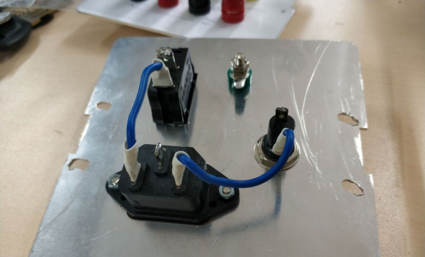
Once all components are soldered, progress to the front and back panels. The casing, pre-manufactured, features aluminum white panels for both front and back. The back panel comprises an input socket, switch, fuse socket, and ground terminal.
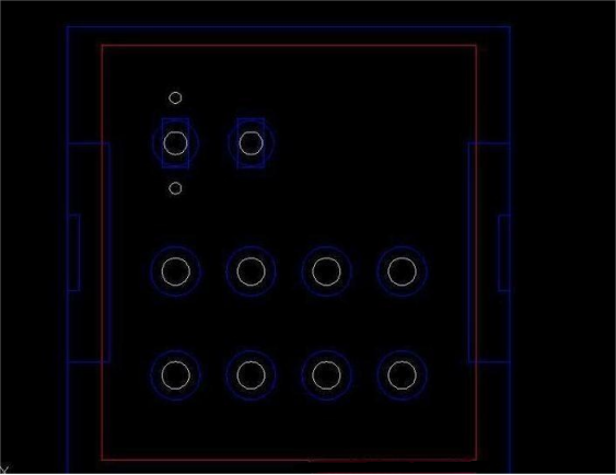
The front panel accommodates positions for 8 terminal blocks, two toggle switches, and two reserved indicator light locations.
After assembling all components, connect the green terminal blocks to the ground terminal using a green wire.
The back panel, constructed from a smooth aluminum plate, adopts an Agilent style without painting. However, the front panel employs white paper printing covered with a plastic film, secured with rod clips.
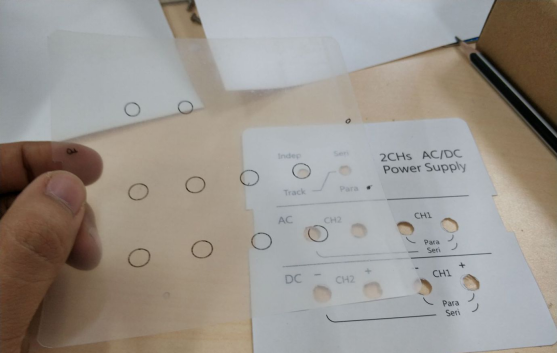
Finally, start placing the components.
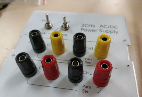
U-shaped forks are used for terminal blocks for added stability. The red and black wires are silicone wires. The mode-switching toggle switches use aviation wires.
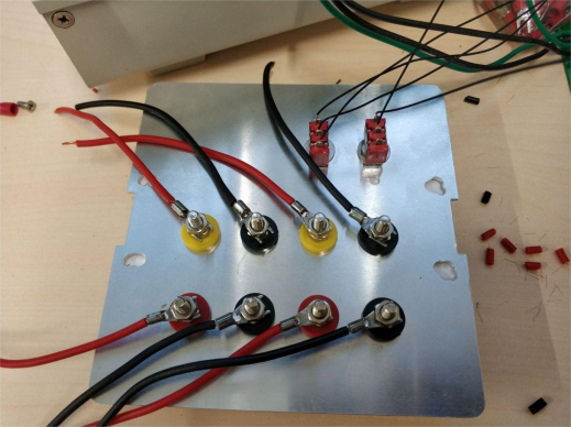
In the final assembly, place all components inside the casing.
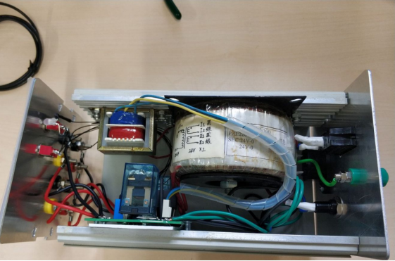
Due to the casing's relatively compact size and the inconvenient position of the rail groove, meticulous spatial arrangement is imperative. The transformer can only be placed vertically with a 1mm gap.
After the final assembly, when positioned alongside the GW Instek single-channel power supply, it demonstrates a more compact form factor, blending seamlessly.
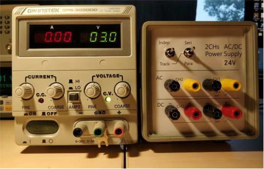
Conclude the process by conducting a test. Given that the transformers or rectifiers provide a direct output, a preliminary measurement is conducted without considering decimal points.
DC Independent Mode
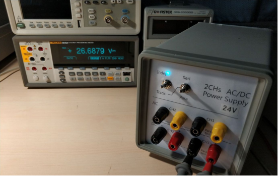
AC Independent Mode
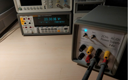
DC Series Mode
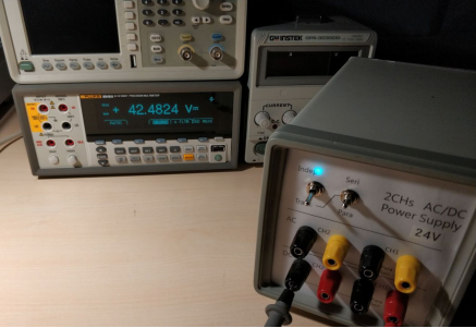
AC Series Mode
