
If your car has a dual lithium battery, using this power supply with the original 3A charger might be a bit slow in emergencies. Sometimes, during the day, there's only half a day to get ready to go out, and time is definitely not enough. So, you need a high-current charger.
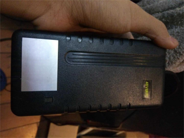
The original charger is 3A, and the power supply has pin contacts at the back. You need to remove them.
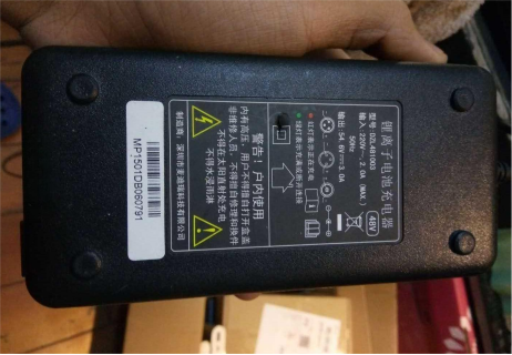
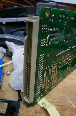
First, use pointed pliers to pull out the pin contacts, then heat them from the back with a soldering iron to remove them.
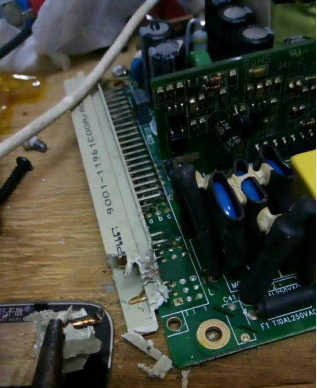
Many have already been removed. Thickened PCB + thickened copper foil + lead-free solder.
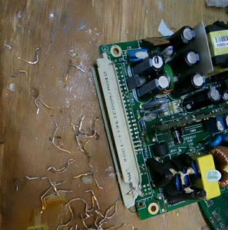
Take a closer look; the contact points at the front are gold-plated.
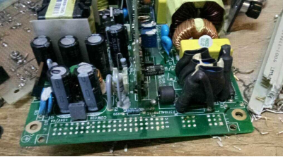
All have been removed.
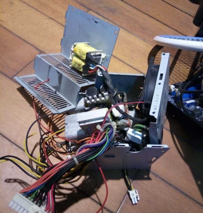
Find an unused computer power supply.
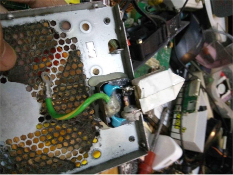
Remove a power supply socket.
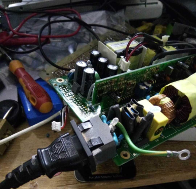
For convenience, it can be designed as detachable.
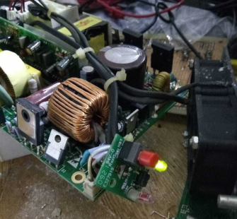
Plug it in to test; it works fine.
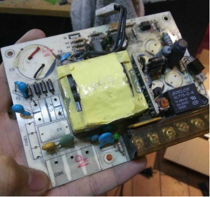
Found an unused power switch, removed a terminal block.
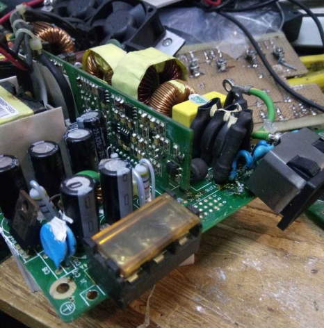
Installed it, positive on the left, negative on the right, and suspended in the middle for stability.
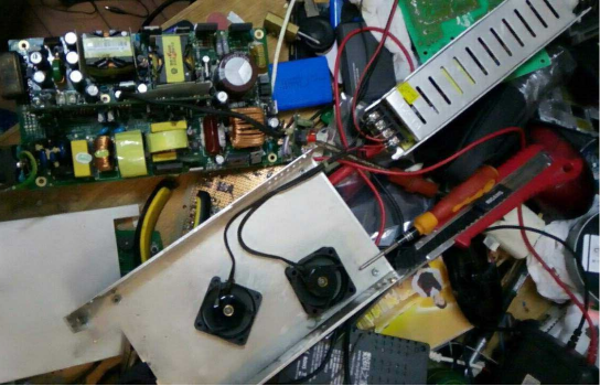
Removed two fans and tidied up a bit.
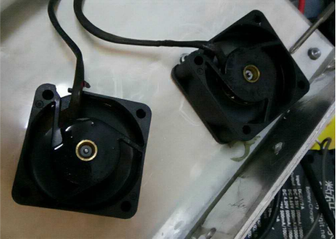
Not many changes made; it can be put back together.
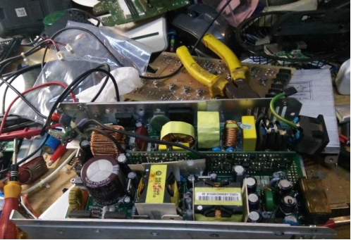
Grounding the power switch is crucial. In case of a short circuit, things could get electrifying. The tail of the copper nose is too long, cover it with heat shrink tubing to prevent contact with other objects.
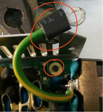
Screw it on without touching anything else.
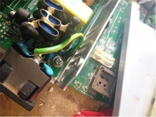
Power on, everything is normal.
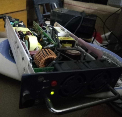
There are two adjustable resistors, the one on the right adjusts the voltage.
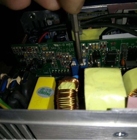
Adjust it to the appropriate voltage for charging an electric vehicle.
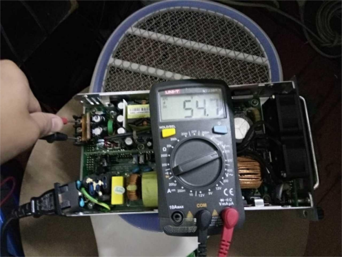
The back cover needs some sawing.
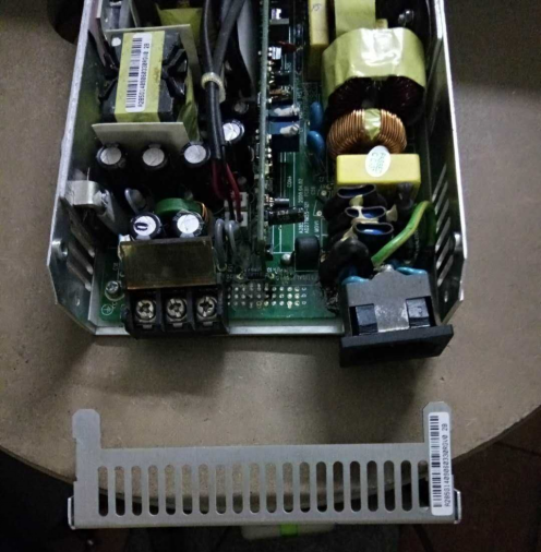
There was a calculation error on the power input side, an extra bar was opened, so be careful when modifying it yourself.
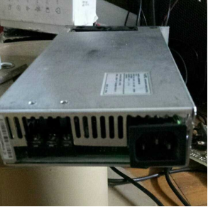
It's tricky to screw on the power output side. Two holes were drilled on top for easier screwing.
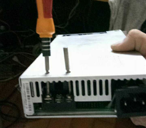
Now, you can start the load test.
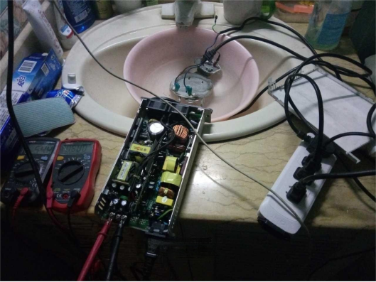
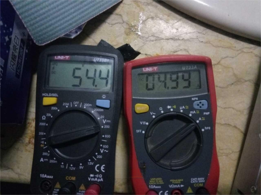
Exactly 5A, loaded for 2 hours, even with that faulty fan, the heat dissipation is still acceptable.
PS: There is a flaw in the output wiring terminal because the terminals are directly soldered on the surface. If not fixed with glue, the wires might come off with a tug. If you don't have epoxy, you can drill a large hole with an electric drill, turn the "surface-mounted component" into a plug, and then solder it in for a secure connection.


