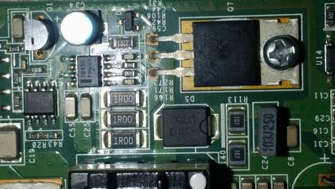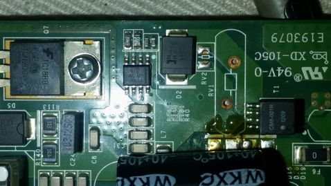
If you have two SGR-W500-N82B dual-band Fat APs powered by 48V, it may be inconvenient for regular use. You could attempt converting them to 12V power. For example, you could add a 7812 voltage regulator or use a 12V to 5V DC-DC converter. However, the circuit board uses a UC3843B DC-DC switching power supply, so you'll need a different approach.

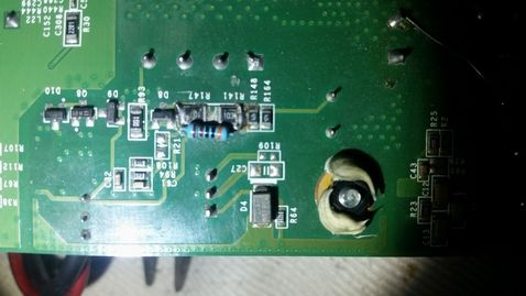
Since it's a switching power supply, you can change the transformer's coil turns to adjust the voltage, ensuring that the UC3843 starts and operates normally at low voltage. You can begin by removing the transformer’s outer feedback winding (14 turns) and primary winding and then rewind the primary winding to 15 turns and the feedback winding to 14 turns. Reassemble the transformer and check the circuit. The UC3843 startup resistors are R141 in series with R147, with values 103+103=20K. According to the UC3843 startup threshold of 8.5V and 1 mA current, you can calculate the resistance as (12V-8.5V)/1mA=3.5K, resulting in a final resistance value of 3K. Connect the resistors R141 and R147 in parallel.

Power up the device. If it doesn’t work, measure the main filter capacitor. If there's no power, the issue may lie with U14, likely due to an under-voltage protection switch. In that case, you may need to bypass its control.


Test the setup again; everything should work fine now. Modification completed.
This process can be labor-intensive, especially since it involves disassembling and rewinding the transformer. If this seems tedious, you can simplify the process by keeping the transformer coils as they are if the turns are close enough. Power up the device and see if it functions normally. You can also test it with a variable power supply, adjusting the voltage as low as 10V to see if it still works. Removing the diode D20 near the power socket might allow for even lower voltage operation, though it isn’t necessary. It helps protect against reverse polarity. Since you only bypassed the under-voltage protection switch and reduced the startup resistor, the UC3843 can handle supply voltages up to 30V. Therefore, this modification should allow the AP to work within a 10-30V range.
Additional notes:
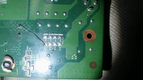
The diodes on the board (D11, D12, D16, D17, D14, D15, D19, and D19) are for POE power supply. Remove them as they are unnecessary.
Removing diode D20 can improve low-voltage power supply performance. Lower voltage will result in higher current, and diode voltage drop can be significant, affecting heat stability. Over time, the increased voltage drop may cause lower switching power supply voltage and increased current, possibly leading to failure.


