
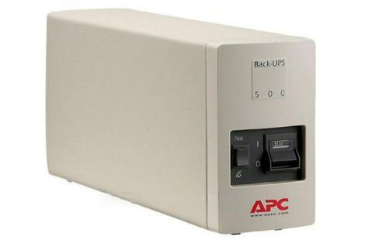
This article describes the modification of an old Schneider model, BK500 MICH, as shown in a similar image.
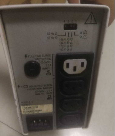
Back Side
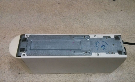
When flipped over, it appears as follows, with the left side being different. The battery is old and has been replaced, but the light doesn't turn on after testing. You can use the transformer's housing to save space.
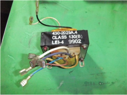
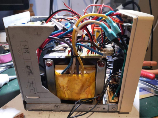
The transformer uses EI96 silicon steel sheets, and its estimated power is about 150W. After measuring, the yellow, purple, and white wires form one set with a purple center tap. The voltage from yellow to white is around 16V, while the voltage from brown to blue is 19V. This results in an approximate rectified and filtered voltage of 22V for the yellow and white wires, which can be used to power two T12s.
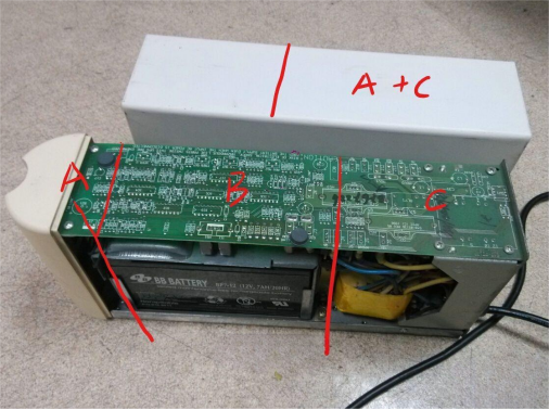
After removing the circuit board, the B section was cut off, and sections A and C were joined. The transformer, fuse, and other parts were retained, while the front part of the casing was removed, keeping the back part intact. An angle grinder was necessary for this.
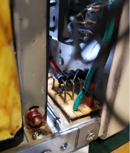
The connection area was secured with M3 countersunk screws and a connection plate made from cut steel. Inside, there's a rectifier bridge from a discarded electric scooter charger with 1N5408 diodes rated at 3A each, making 6A total, which should suffice.
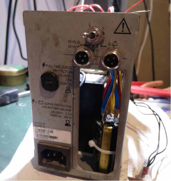
The rear section was fully utilized, and a knob switch was added for controlling one part. It was placed in the original position on the back and slightly enlarged with a drill.
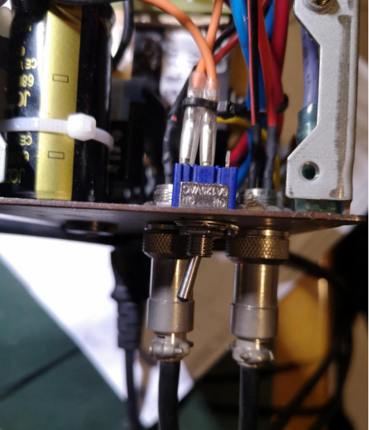
Two 6800uF capacitors were connected in parallel, resulting in 13600uF in total, with RC > (3~5)/2f.
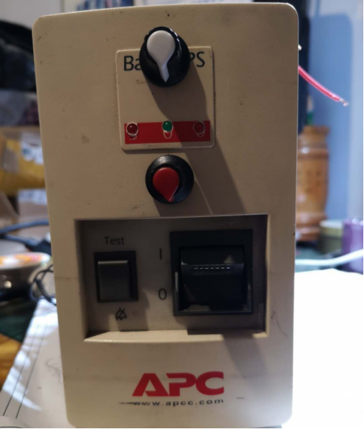
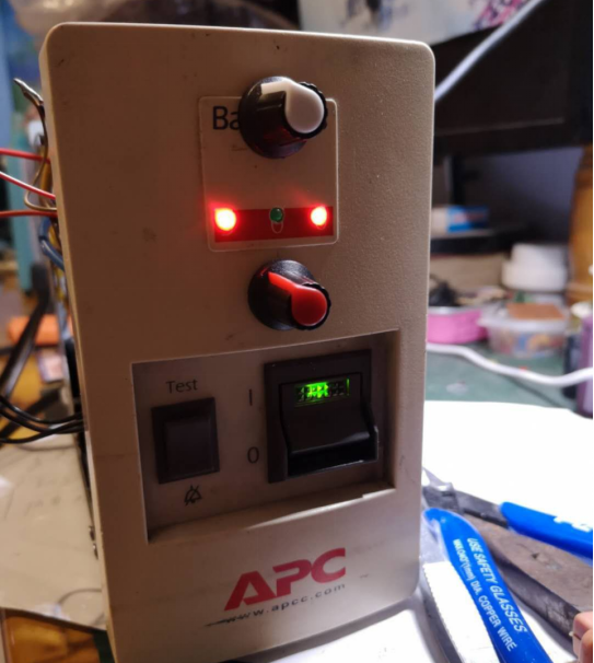
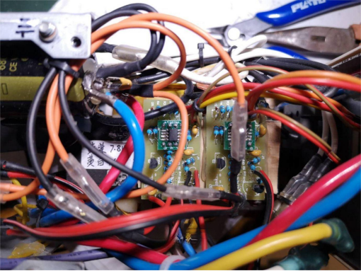
On the front, there are two knobs. The white knob on the left connects to the knob switch, while the red knob on the right is controlled by the main switch. Each character on the 500 mark was given an LED. The left and right LEDs indicate heating, while the center green LED indicates control board power.
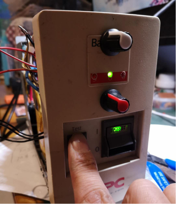
The left TEST switch was used by connecting it to the positive ends of the control boards' power LEDs and a common green LED. This setup indicates when a control board is working, even though it may not have much use.
The main switch has a built-in green LED, powered by the 19V secondary voltage.
Using a wire stripper would be convenient.
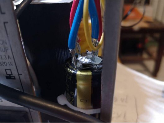
The capacitors were connected using 6.3mm terminal connectors bent at 90 degrees through the central hole.
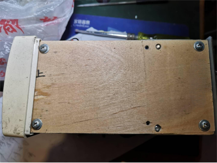
A custom top cover was added.
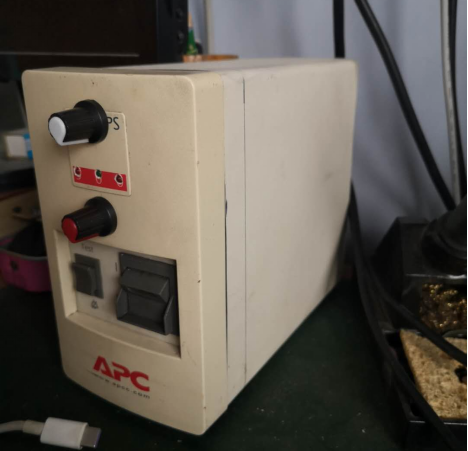
The modifications are complete.


