
The image below shows an old-style breadboard with dual-row socket power connections. The model number is SYB-118.
Pairing the breadboard with a DIY power adapter board can be very convenient, as shown in the image below.
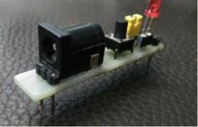
The next image shows a more modern breadboard, featuring dual-row socket power connections at the top and bottom, and including a matching power adapter board. This setup eliminates the need to create a DIY power adapter board, making it more straightforward.
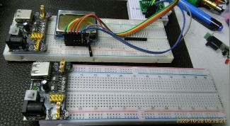
However, the modern breadboard has one shortcoming—it lacks screw fixing holes, even though it does come with adhesive backing. This adhesive tape is essentially a one-time use item.
You can consider creating a new DIY 3.3V power adapter board based on the SYB-118 old-style breadboard.
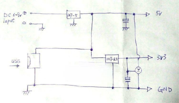
For power supply, if you have a USB/portable charger that provides 5V, and you also have a small DC power supply available (6V, 9V), as well as a spare 2S battery, you can add an additional three-terminal regulator.
It's crucial to monitor the 3.3V output, so attaching a meter would help you keep an eye on the voltage output. During the build, you can add a jumper cap to the power supply on the meter, allowing you to enable or disable the connection as needed.
Circuit diagram:
A small piece of perfboard was chosen to avoid taking up too much breadboard space; the width doesn't exceed the first 5 holes of the left section.
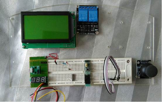
All the experimental equipment is mounted on a 3.5mm thick transparent acrylic board.
Before attaching the meter:
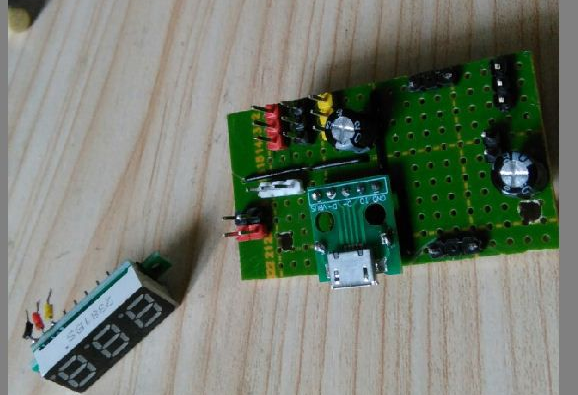
Several soldering holes were drilled along the edge of the perfboard, using a 0.5mm diameter drill bit.
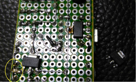
If, after finishing and testing, the 3.3V output isn't right (e.g., it goes above 4V), check the meter or other components. The problem might be with the 1117-3's left pin, which should be connected to GND. If that's the case, the 1117-3 might be faulty and should be replaced with a new one. Solder the new 1117-3 in the indicated position in the image below.
The setup is powered by a 2S battery and tested. The sunglasses in the foreground are used for the testing.
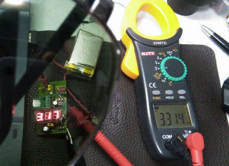
Remember to add two layers of optical filters.
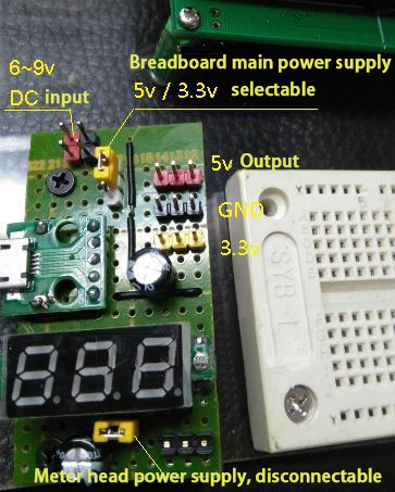
There are three sets of headers at the top:
· Yellow: fixed 3.3V output
· Middle (black): GND
· Red: inserted into the positive main power rail on the breadboard, allowing you to select between 5V and 3.3V via jumper
The DC power supply for this SYB-118 breadboard has one line of routing at the top and bottom.
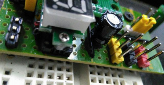
Completion
* Note: Keep DuPont wires and connecting wires straight and untangled.


