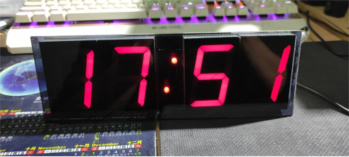
If you happen to have a few 2.5-inch common anode LED displays, you can DIY a clock. You can search online for related C programs and open source files.
For the PCB and schematics, refer to the following two diagrams:
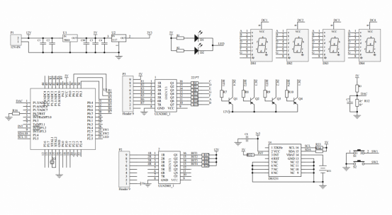
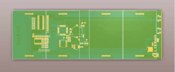
If you're planning to DIY, make sure to carefully read through and understand the tips provided below.
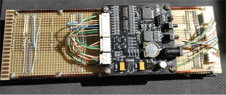
After creating the PCB (main control PCB), gather the necessary components such as DS3231 and solder them together.
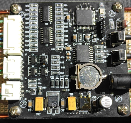
The LED display is installed on a perforated board. Be mindful of the wiring when installing it; in the open source PCB files, the LED display is depicted on the front of the PCB, but it should be installed on the back of the PCB. Be sure to pay attention to the wiring method to ensure proper functionality.
Reverse the wiring order as follows:
F → A
G → B
E → C
D remains the same
A piece of brown acrylic was cut for the front cover and glued with 502 glue. There is a small mark from the glue on the front corner, and the brown acrylic isn't very clear.
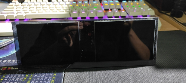
Power it on, and you're done!
