
The USB light uses LED light source, with high brightness, low power consumption, and compact portability. It can provide temporary lighting wherever there's a USB interface, whether as a bedside lamp, for walking at night, or during power outages. The small USB light proves incredibly useful in various situations.
Firstly, the first type of DIY USB light:
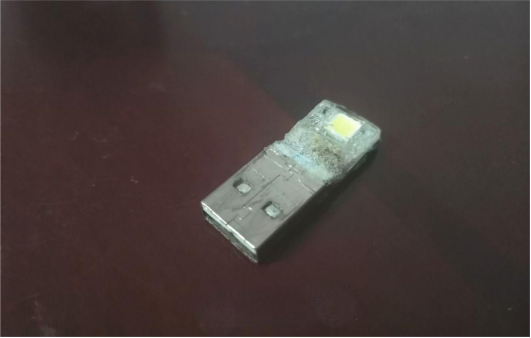
This USB light is quite simple, comprising only one LED and a current-limiting resistor, mounted on a discarded USB plug and sealed tightly with transparent plastic.
The lighting effect is shown in the picture:
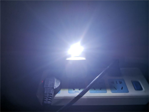
While this USB light has a high color temperature, it's somewhat outdated. We need to redesign a multifunctional USB light that can serve as both general lighting and a nightlight, with added light control features—automatically turning off during the day and on at night.
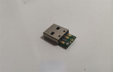
Firstly, obtain a USB plug core with gold-plated contacts, ensuring decent quality:
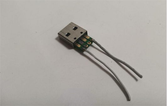
Solder on two wires for testing, remove excess parts from the plug core, and re-solder the wires:
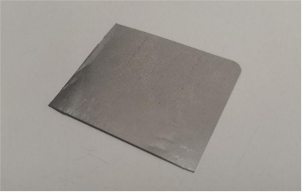
Find a piece of alloy material from a SONY floppy disk, which is non-magnetic with good elasticity, suitable for DIY:

Flatten it out, cut a piece, and then process it:
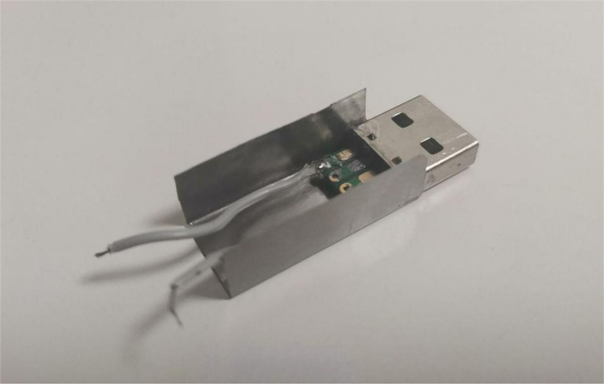
Based on the dimensions of the USB interface, bend it manually, insert the plug core, and adjust:
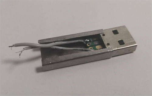
The plug core fits snugly; bend it again to form the shell, ensuring it covers the USB plug well. Trim off any excess, leaving ample space for light emission:
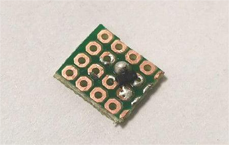
Find a piece of fiberglass perforated board, cut it to size, about 4x4, for installing the control circuit. Then, find a MOSFET transistor, A1SHB type, a P-channel MOSFET suitable for low-current applications, and solder it in the appropriate position on the board:
Solder on a resistor:
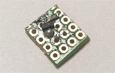
Remove and trim a photosensitive resistor, solder it together with a 1M resistor in parallel for the light control circuit, completing the soldering of the light control circuit:
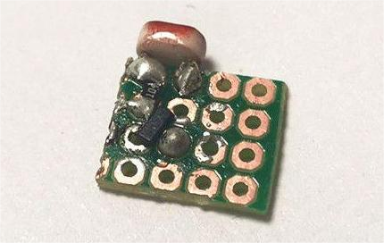
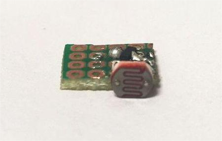
String LED beads together to test the circuit. Under sufficient light, the beads remain off with a current of 0.1mA. In a dark environment, the beads emit some light (sufficient for a small night light) with a current of 10.5mA. The light control circuit is successful:
Adjust the resistance connected to the gate to ground to adjust the light control's illumination threshold (light below this threshold turns on, above it turns off). A 70k-ohm resistor is recommended here:
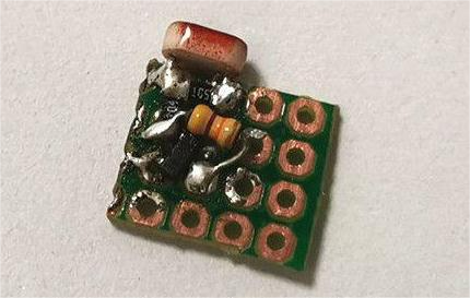
Due to the light's "one-key ultra-bright" function, a button switch needs to be installed. Solder it to one corner of the board and add two current-limiting resistors (4.7 + 4.7 ohms initially, later changed to 5 ohms due to insufficient brightness):
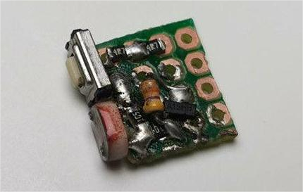
Solder three wires onto the main board, as shown in the diagram:
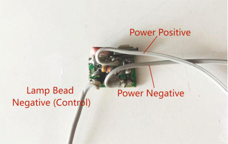
Take an Osram LED bead, stick it under the board, and solder the negative lead of the bead:
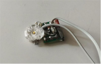
Solder on the USB plug (trimming off excess parts to fit into a tight space):
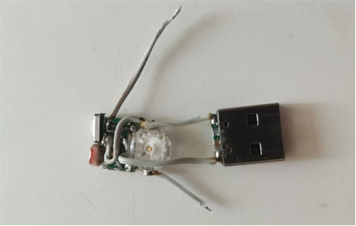
Solder on a PCR606J thyristor, providing the "one-key ultra-bright" function. When the button is pressed, the thyristor triggers conduction, short-circuiting the light control circuit in parallel, allowing the LED to run in ultra-bright mode. Due to the 5-ohm current-limiting resistor and good LED heat dissipation, ultra-bright mode poses no harm to the LED. After reinserting the USB, the thyristor stops conducting, and the light control circuit resumes operation, returning the light to light control mode:
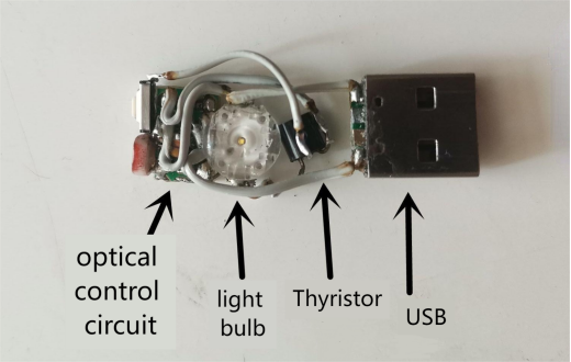
The PCR606J unidirectional controlled silicon/thyristor must be insulated for heat dissipation, with tin applied to the LED heat sink position for soldering the heat dissipation copper foil:
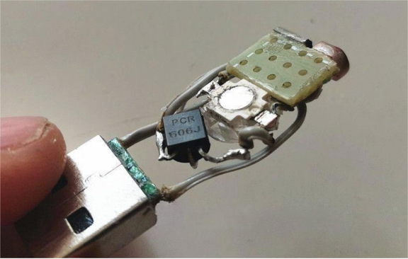
The back of the LED bead is soldered with copper foil for better heat dissipation. Apply thermal conductive silicone grease, assemble the light core into the shell, ensuring the USB plug core fits snugly and is reinforced with 502 glue, as shown below:

Apply glue inside the light core, then affix two iron pieces to cover the internals, exposing a light emission window and affixing a semi-transparent plastic as a soft light film, then another semi-transparent plastic for soft light and aesthetics, completing the multifunctional USB light. The finished product is shown below.
Front view:
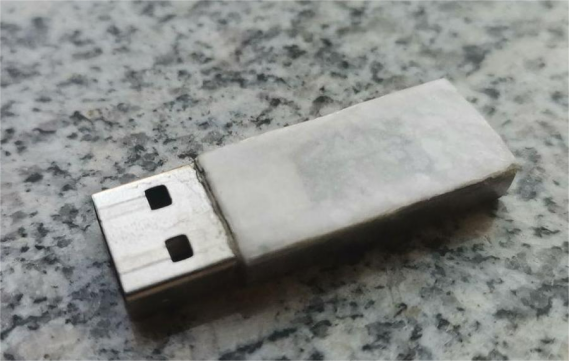
Back view:
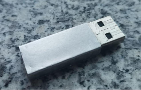
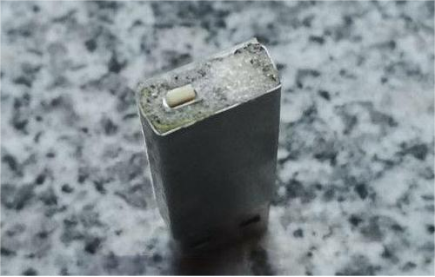
Top view with light-sensitive area and "one-key ultra-bright" button:
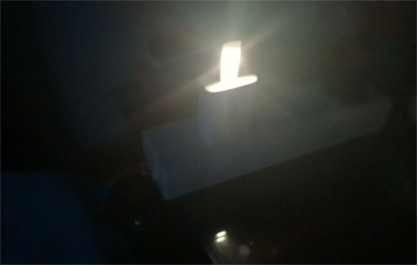
Nighttime illumination effect (night light mode):
Circuit schematic:
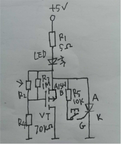
From the diagram, it's clear that the USB's 5V power passes through a 5-ohm current-limiting resistor and LED into the control circuit. The control circuit splits into two paths: the left for light control and the right for thyristor trigger circuit. When R2 photosensitive resistor receives sufficient light, its resistance decreases, causing the P-channel MOSFET gate potential to rise and cut off, turning off the night light. In very dark conditions, R2's high resistance pulls the gate potential low via R4, causing conduction, thereby turning on the night light. Regardless of whether the night light is on or off, pressing the trigger button triggers the thyristor to conduct, short-circuiting the light control circuit, allowing current to flow directly through the thyristor and enabling the LED to operate at full power in ultra-bright mode. After a power outage, the device resumes light control mode.
Finished


