
How to make a PWM speed control circuit with LM324?
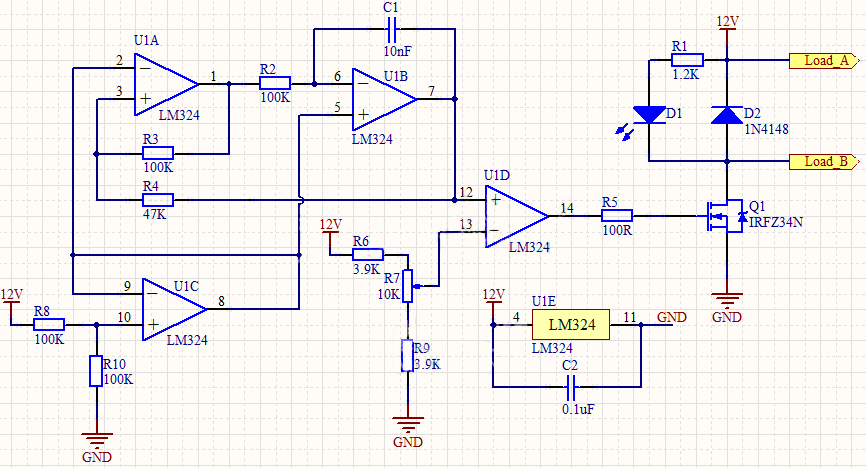
First, let's look at the schematic diagram:
Circuit Diagram Function:
This circuit consists of an LM324 and a MOSFET. By changing the duty cycle of the output square wave, the average on-time of the load varies from 0 to 100%, achieving speed adjustment.
Circuit Diagram Explanation:
The circuit uses LM324 to form four different functional modules:
· Reference Voltage Generation: U1C generates a 6V reference voltage, which serves as the reference voltage for the oscillation circuit.
· Oscillator Circuit: A hysteresis comparator (U1A) and a triangular wave generator (U1B integrator circuit) are connected in series to form a waveform oscillator.
· Voltage Comparator: U1D acts as a voltage comparator. The voltage divider network (R6, R7, R9) provides the reference voltage to the comparator.
· The output of comparator U1D is connected to a gate resistor (R5) of the MOSFET Q1. The square wave output from the comparator drives the on and off states of Q1. The reference voltage provided by the voltage divider network (R6, R7, R9) is compared with the triangular wave output from U1B. When the triangular wave voltage is higher than the reference voltage, the comparator outputs a high level, turning on Q1, and creating a current loop in the load. When the triangular wave voltage is lower than the reference voltage, the comparator outputs a low level, turning off Q1 and cutting off the load's current loop.
· An LED (D1) indicates when the load power is on. The diode is necessary for inductive loads to protect the MOSFET Q1.
· The load can be a motor. By changing the reference voltage, you can adjust the high and low-level output time of comparator U1D, thus changing the motor speed. If the load is a light bulb, adjusting the reference voltage will change its brightness.
Attention:
The power supply for this circuit is 12V, suitable for a 12V motor or other loads with the same rated voltage. You can also modify it for 24V. The triangular wave frequency is fixed in this circuit, but you can modify the circuit to make the frequency adjustable.
Start by planning the layout carefully to avoid flying wires and ensure success in the first attempt. Optimize the layout further if possible.
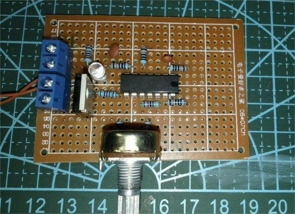

Instead of a motor, you can used a bulb as the load for testing.
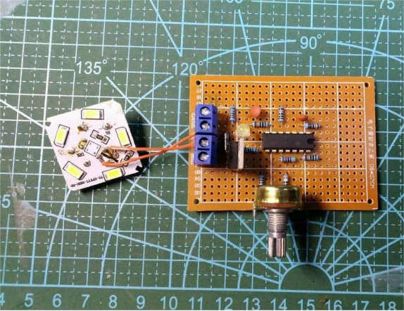
Apply power and check the circuit. Ensure the diode is soldered correctly.

With a supply voltage of 15V and a current of 20mA, adjust the potentiometer to the minimum, and the bulb doesn't light up.
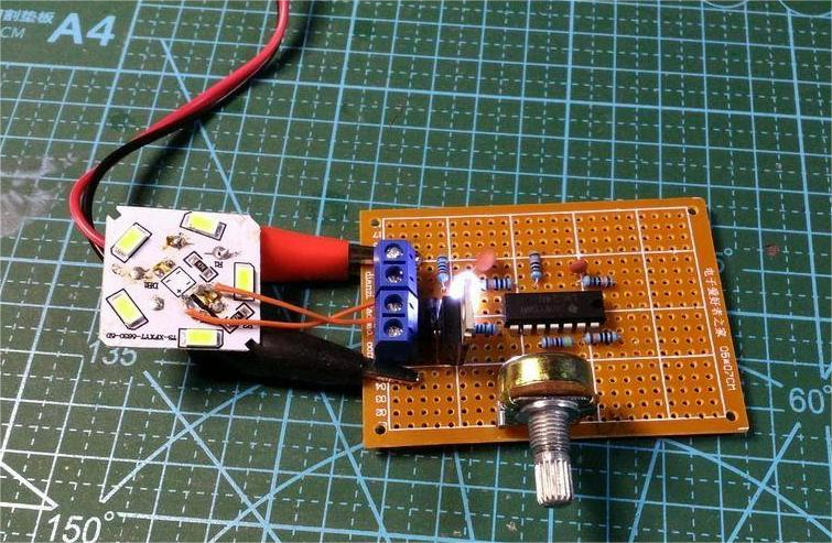
Gradually increase the potentiometer until the bulb shows a change in brightness.

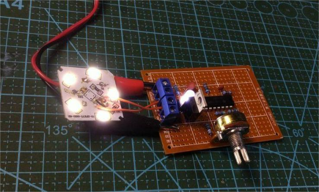

Test complete. If you have more time later, you can make the circuit smaller and optimize the layout further.


