
How to make a QC3.0 charger voltage manipulator? Try laser engraving method.
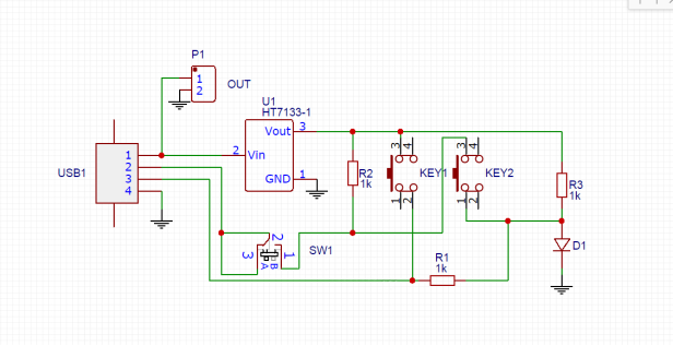
Schematic
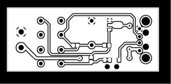
PCB
Laser-engraved PCB board; the engraved circuit looks like this:
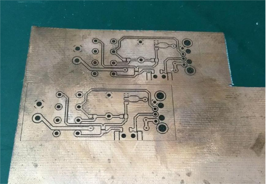
Cut and trim the shape, then drill holes.
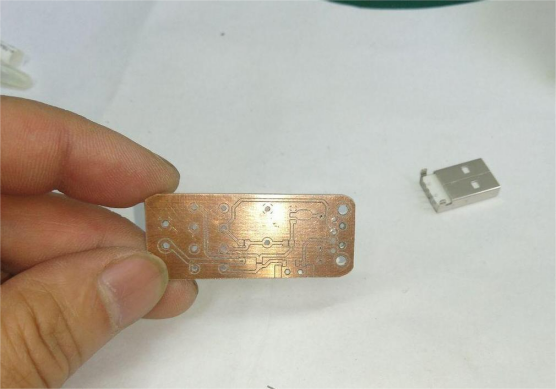
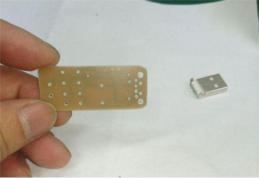
Checking Light Transmission: The laser parameters are not optimal; some areas were not cleaned thoroughly. If there are copper shavings, use a blade to clean the gaps.
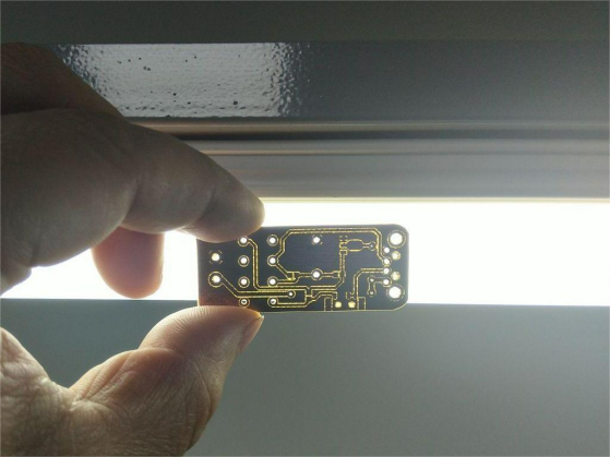
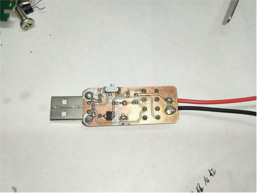
Soldering Components: Those two wires are jumpers. You actually need three wires. If you miss one during assembly, you can add a wire directly on the back.
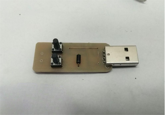
Back Side
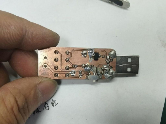
Solder the output wires. The output wire design uses 5.08mm pitch, allowing for terminal blocks.
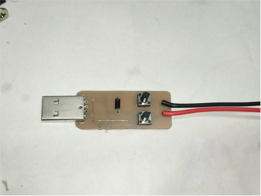
Normal State (No Load):
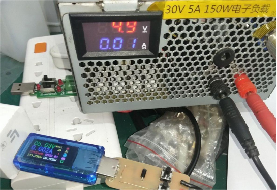
QC3.0 State:
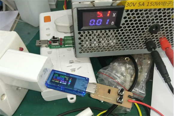
Each press increases the voltage by 0.2V with an error of +/-0.01V. Sometimes it's 0.19V or 2.01V.
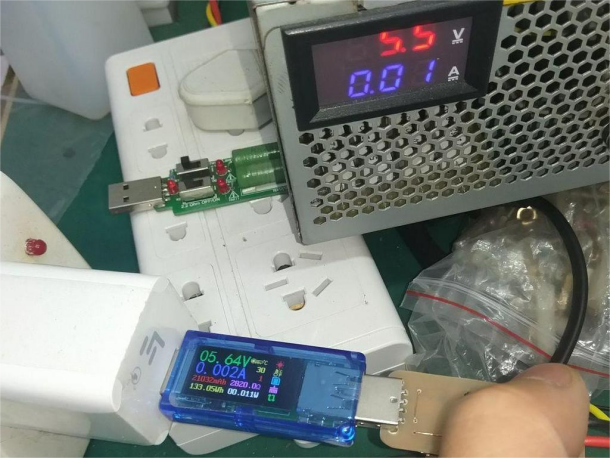
Continuous Voltage Increase
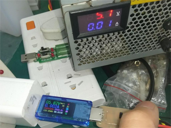
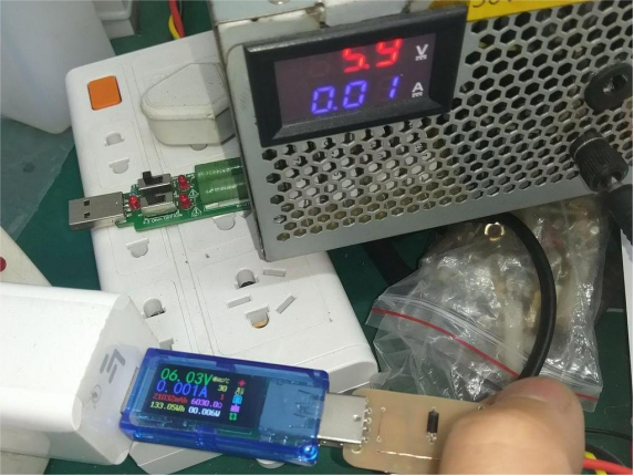
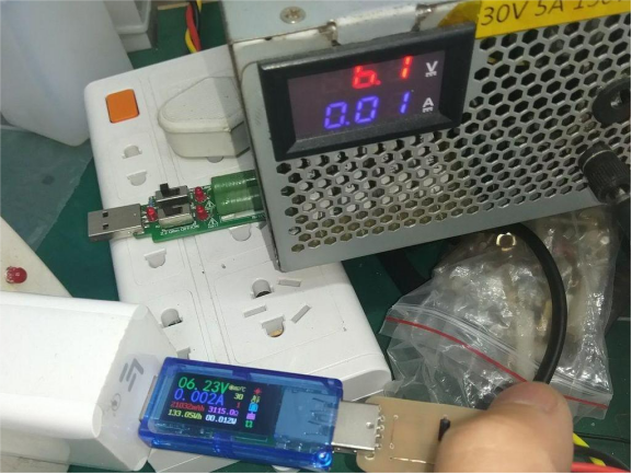
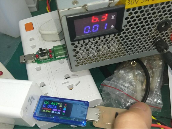
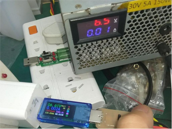
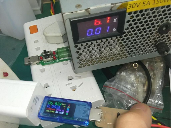
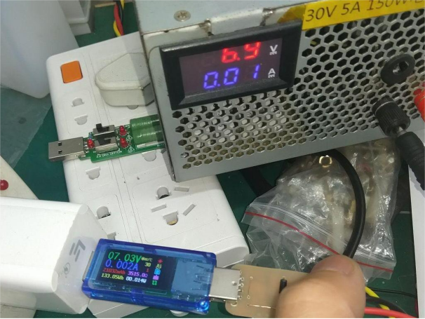
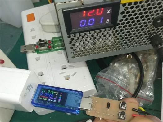
Highest Voltage: 11.97V
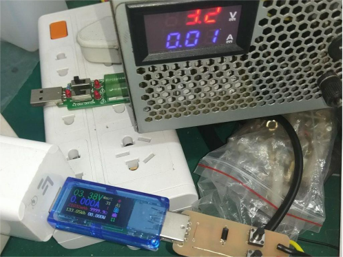
Lowest Voltage: 3.38V
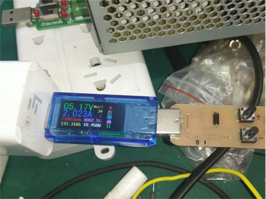
Load Test Begins: 2A, Normal State
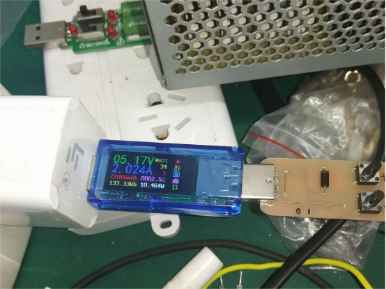
Switch to QC3.0 mode; voltage remains unchanged.
Press once to decrease, and the voltage drops to 4.99V.
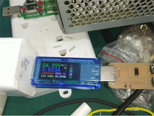
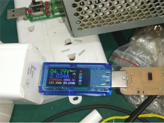
Press again to decrease, and it drops to 4.79V.
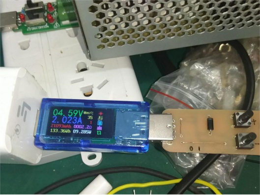
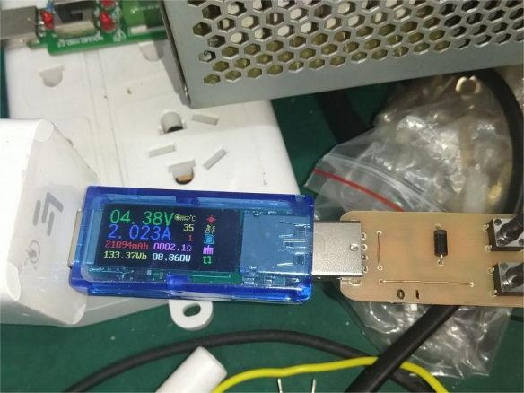
4.20V – Adding a resistor allows it to charge lithium batteries.
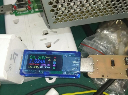
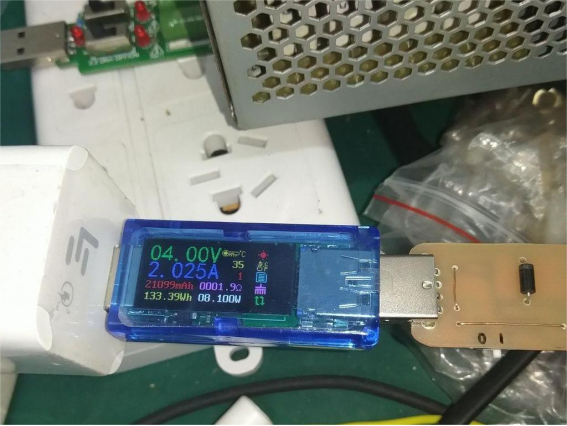
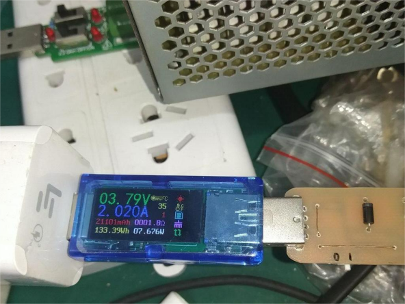
Under load, the voltage can only drop to 3.79V.
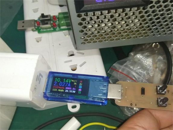
Increase the voltage: 10.14V
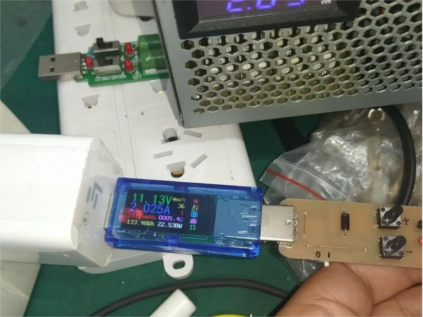
11.13V
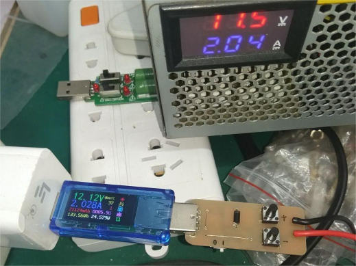
Highest Voltage: 12.12V
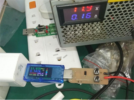
At low current, the highest is 11.97V. The extra 0.15V accounts for line losses at 2A current.
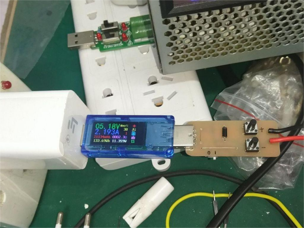
For 8V at 3A, if the current increases further, the charger will protect itself.
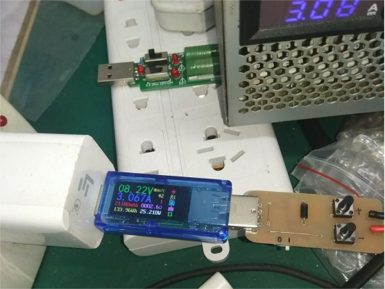
Switch to Another Charger: This one seems to be QC2.0. Output parameters are labeled as 5V2A or 9V1.67A.
5V No Load
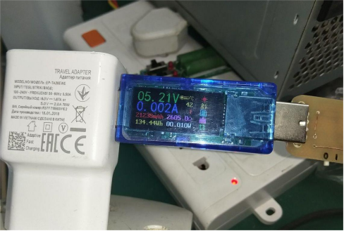
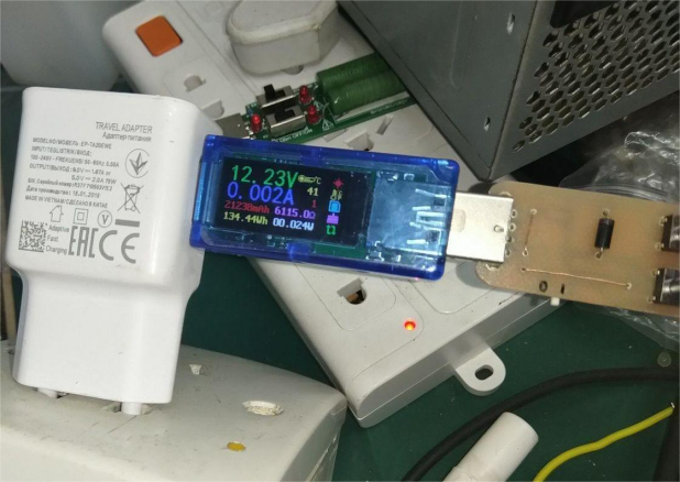
Press either button, and the output voltage jumps directly to 12V. Pressing again has no effect unless you switch the QC trigger back.
12V Under Load: 1.7A
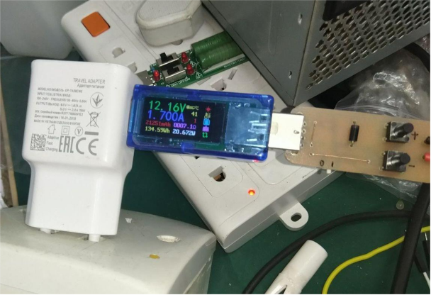
It reaches 2A, but after a while, it enters protection mode, possibly due to transformer overheating.
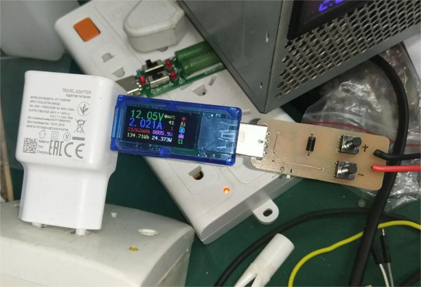
Finished.


