This article will detail the modification of the Xiaomi Redmi Xiaoai Touchscreen Speaker by adding a battery. The motherboard has a battery interface, so adding a battery is feasible.
Components Required:
· 3MM red-green dual-color LED
· Battery: Supfire 26650 with a nominal capacity of 5200mAh
· Board: 12W DC UPS V2.0 power supply module, 12V uninterruptible power control board, output 9V or 12V
· Switch: Touch button switch module, 3V-30V momentary/latching
· One relay
Let's first discuss the board. It is highly functional, automatically switches to battery output during a power outage, and comes with a protection board.
The dimensions are shown in the following image:

Board Interface Diagram:
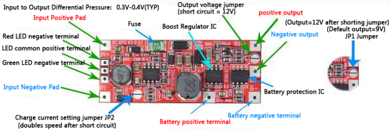
The default charging current is 0.6A, which takes about 15 hours to charge a 6000mAh battery. By shorting JP2, the charging current increases to 1.2A. If you need to connect an external jumper wire, you can parallel a 1-100NF ceramic capacitor on the jumper to counteract signal interference.
Important Considerations When Using This Board:
· The power input end has reverse polarity protection, so occasionally connecting the wrong polarity will not damage the chip, but it should not be reversed for long periods. The battery end has no reverse polarity protection.
· Battery lead issues: The motherboard's full-load startup current is about 6A, and continuous operating current is 3A or less, so the battery leads must withstand 6A of current.
· Battery range: By default, it supports slow charging mode and can support 3000-6600mAh lithium batteries. The charging current can be adjusted to expand the battery capacity range.
· System switching: The motherboard switches seamlessly without delay, and the switching threshold is referenced to the input voltage, switching to battery power when the input voltage drops by 10%.
· If you need to connect a fan or motor, you should add a tantalum capacitor for filtering.
Switch:
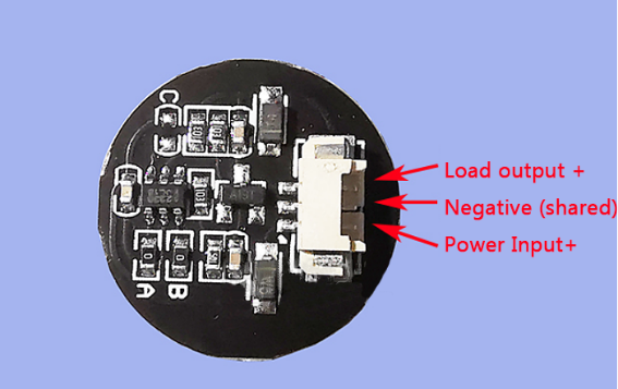
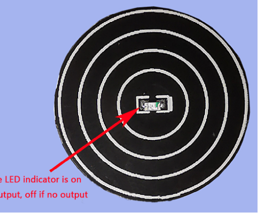
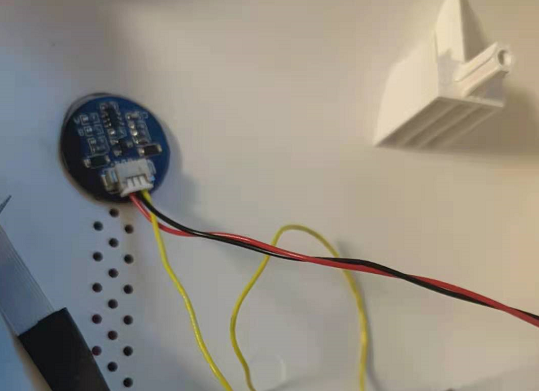
Touch button switch module, 3V-30V momentary/latching (If you don’t want to damage the speaker casing by installing a switch, this can be attached to the back cover of the speaker with double-sided tape, with an 8MM sensing distance).
Relay:
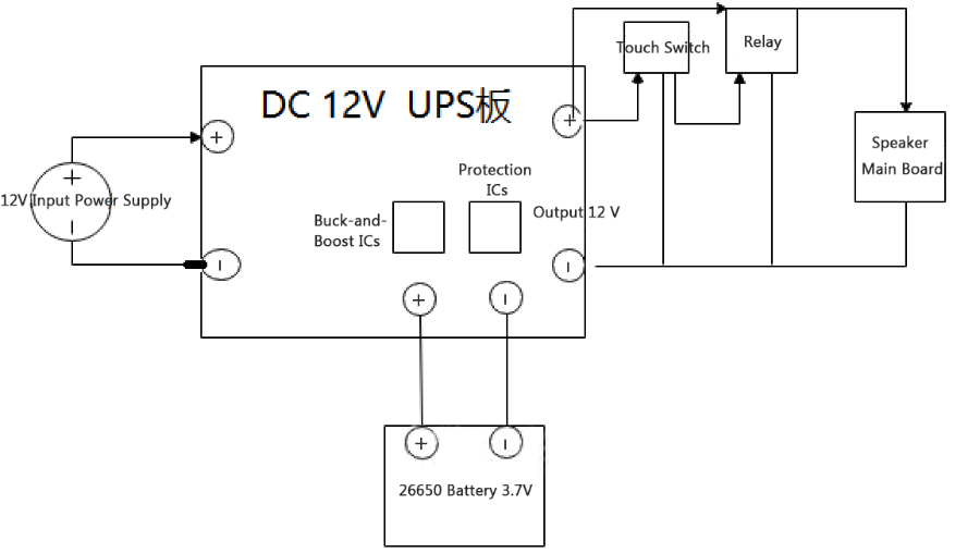
One relay: Initially, without a speaker connected, using the touch switch was problem-free. Once the speaker was connected, the load increased beyond the touch switch's maximum load current, causing power cuts when the volume was high. A relay was needed to drive the relay.
Steps:
1. Connect the Battery:
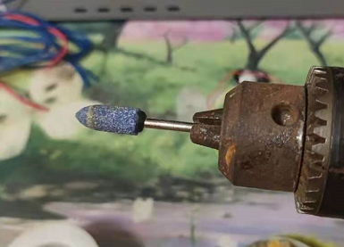
If you don’t have a spot welder, the 26650 battery electrodes might be difficult to weld. You can use a small grinding rod to roughen the surface for easier welding.
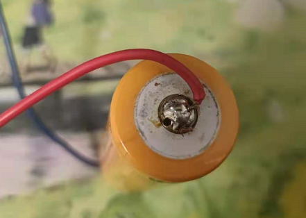
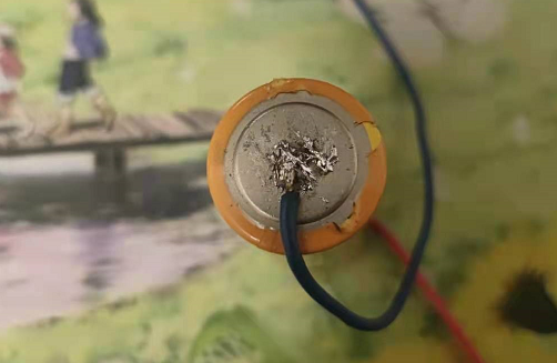
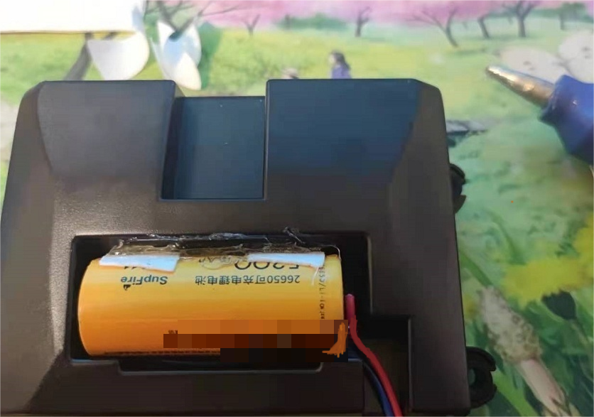
The battery slot reserved in the speaker fits a 26650 battery perfectly. Use double-sided tape to secure it firmly in place.
2. Power the DC Board:
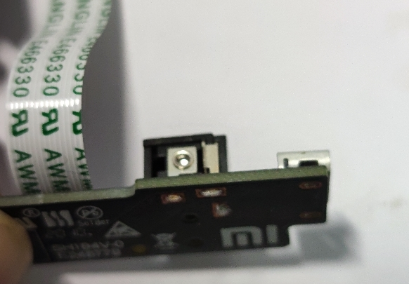
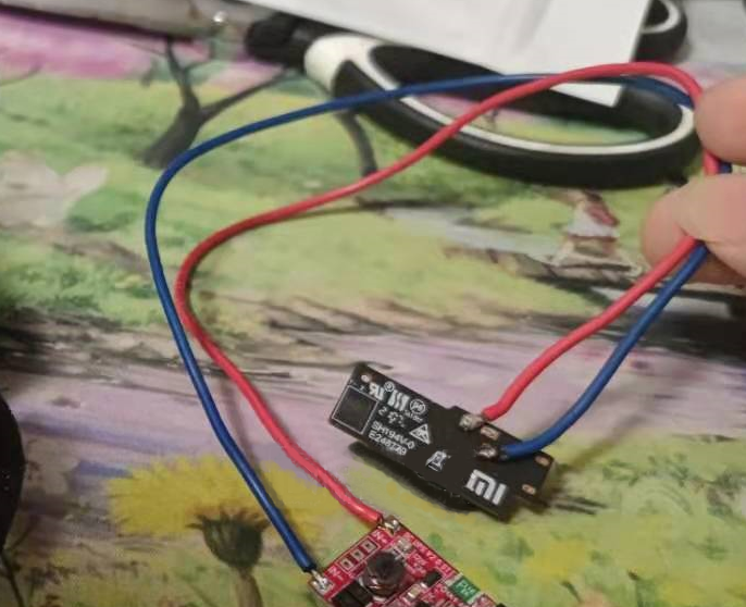
The DC board originally had a ribbon cable for power and data transmission. If you don’t plan to flash the firmware, you can unplug it for now.
3. Connect the Touch Switch:
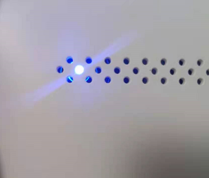
When the touch switch is touched, the light turns on, indicating a powered state. Touching it again turns off the light, cutting the power. This does not damage the casing.
4. Overall Wiring:
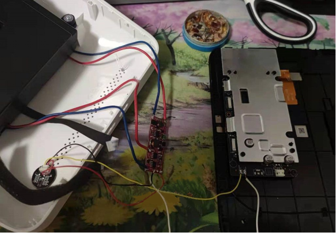
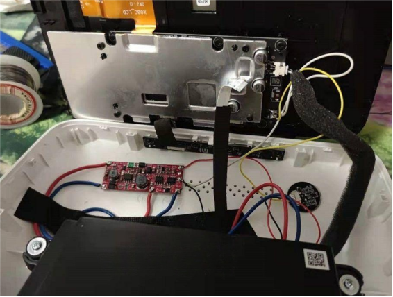
Perfectly test the system without connecting the speaker. If connecting the speaker exceeds the touch switch's power limit and cuts off power, add a relay.
5. Completion:
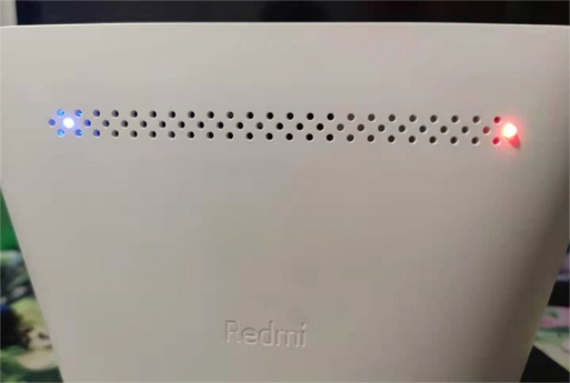
The blue light is the touch switch, on when powered and off when shut down. The red light is the charging indicator, turning green when fully charged and off when switching to battery power.
Finally, here is the circuit diagram of the completed product:
