A voltage and current meter is a frequently used tool in DIY projects. However, most commercial meters only display voltage and current with limited accuracy—using a TL431 is already considered decent, and better options usually rely on an LM385 reference, which isn't sufficient for serious work. Additionally, connecting these meters can be cumbersome. When measuring power supply currents, everything is combined, making it easy to burn out the circuit with a careless mistake. There are meters with isolation modules that are safer, but these typically can only measure voltage or current separately, requiring you to purchase two if you need both measurements. So, let’s take a look at this high-precision DIY voltage and current meter. Please note that this instrument has some risks associated with its use, and it's not advisable to replicate it without caution.
Specifications Overview

As with any instrument, precision is key. The accuracy of a voltage and current meter is determined by the voltage reference, voltage divider resistors, and shunt resistors. Why not mention the ADC? For a four-and-a-half-digit meter with a measurement range of 32V, a 16-bit ADC is more than sufficient. Fortunately, 16-bit ADCs are now quite mature, and most available models meet these requirements.
Regarding precision, the voltage reference is crucial. We won't be using LM385 or TL431 anymore. Although AZ431 claims a temperature drift of 20 ppm, real-world tests reveal its performance is rather mediocre. Texas Instruments components are generally more reliable, especially in the analog realm. After testing, the REF3325 proves to be more suitable, with a typical temperature drift of just 9 ppm and a maximum of 30 ppm, as detailed below:

Long-Term Stability: Only 55 ppm variation over 1000 hours.
Consistency: Most variations are below 10 ppm, rarely exceeding 30 ppm, making it a significant upgrade over multiple LM385s.

The voltage divider resistors must also meet high standards. For voltage channel accuracy, their importance is on par with that of the voltage reference.

After testing various precision resistors, this one stands out with a precision of 0.1% and a temperature drift of 10 ppm. After 2000 hours, its variation is just 0.01%, making it a perfect match for the previously mentioned voltage reference. The shunt resistor should also be chosen for minimal temperature drift, although the best available has a drift of only 15 ppm, which is still quite good.
Next, we need isolation. Without it, a simple wiring mistake can fry the meter; thus, isolation is a must.
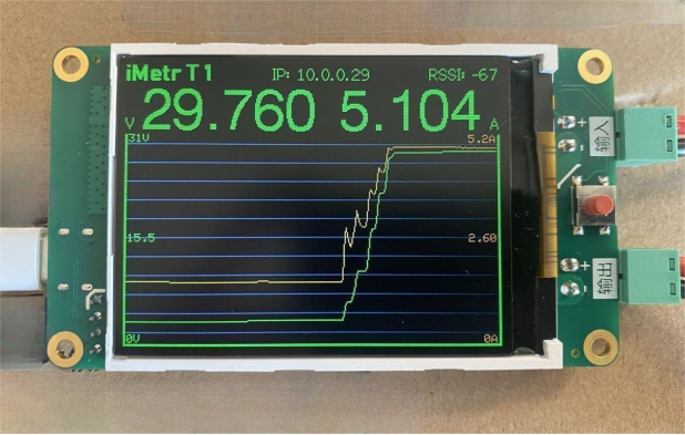
With all components in place, we can't overlook the PCB. We opted for a four-layer gold-plated PCB, incorporated an LCD screen, implemented dynamic scaling curves, and included Wi-Fi connectivity.
Here's what the final product looks like:


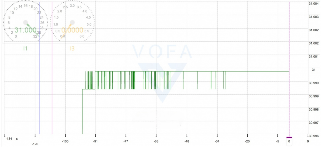
After connecting via Wi-Fi, this isn't just a voltage and current meter anymore. The accompanying software can log hundreds of thousands of data points. It functions as a data logger, power consumption analyzer, and even a capacity tester, allowing users to view curves for voltage, current, power, watt-hours, and amp-hours.

With magnification, you can see the changes in each data point.

This is truly an outstanding voltage and current meter.
In terms of accuracy, after a 30-minute warm-up and calibration, it compares favorably with a six-and-a-half-digit meter, varying only by about one digit. However, needing to warm up is its main drawback.


