DIY 2P3 Radio Using LA1600 and TA7368 Integrated Circuits
If you're interested, read on to learn how to recreate a version of the LA1600 model of the 2P3 radio using the LA1600 chip by modifying the Teesen 2P3 DIY kit.
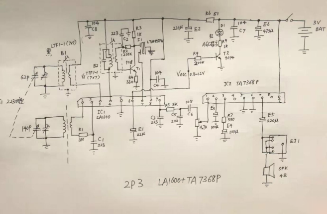
The circuit parameters demonstrate good overall performance. An additional 9018 preamplifier stage has been included, providing a voltage gain of 9dB. This adjustment compensates for weaker signals by slightly enhancing sensitivity without noticeably increasing overall noise.
The TA7368 power amplifier has also been set to achieve a lower gain. A new feature is the LED display for AGC voltage, with a red LED mounted through long pins inserted from the back of the PCB, allowing light to shine through near the volume potentiometer slot.
In practical use, strong signals illuminate the light, weak signals dim it, and no signals turn it off—this proves to be more functional than simply adding an LED power indicator.
For the oscillator and intermediate frequency stages, 7x7 sized LTF1-1 and TTF1-1 coils are utilized. The primary inductance of the oscillator coil is around 400µH, with a turns ratio of 10:1, working effectively with the 144/62P differential variable capacitor. After testing, it was determined that the intermediate frequency stage should be replaced with the TTF1-2, which has a slightly different number of turns but the same packaging. The double variable capacitor has the most significant impact on the overall tuning characteristics of the device; the light yellow double variable capacitor used (which appears to share a mold with a four-section variable capacitor) provides excellent tracking synchronization, outperforming a white 223 pure double variable capacitor across the frequency range, resulting in consistently high sensitivity.
Circuit Diagram:

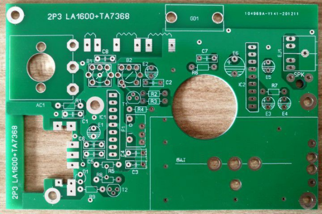
PCB:

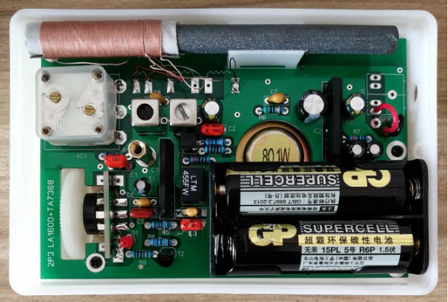
All components should be soldered and assembled into the 2P3 case:

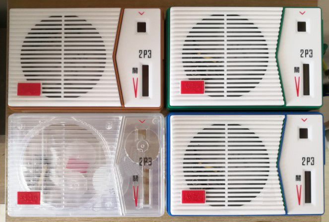
2P3 Case:

Overall Assessment: The sensitivity, selectivity, and background noise levels with strong signals are all superior to those of the original 2P3 kit circuit. The AGC performance is particularly impressive, with minimal volume difference between strong and weak signals. The primary coil of the antenna is directly taken from the Teesen kit, paired with its magnetic rod, although the exact number of turns isn’t counted. However, it’s best to fabricate the magnetic rod coil yourself. For the 144/62P differential variable capacitor, the optimal primary inductance is around 600µH (the coil's position on the magnetic rod can vary by about 20%). The required number of turns differs based on the materials and sizes of the magnetic rod. For the Teesen 2P3 magnetic rod, I estimate the primary is around 120 turns. The secondary coil generally accounts for 15-20% of the primary coil's turns. It’s best to wind the primary in two or three sections. With an inductance meter, it's straightforward to achieve the desired inductance by winding it directly. If you don’t have one, rely on experience: typically, larger magnetic rods need 80-90 turns, while smaller ones require about 120-130 turns.
E2 is a large-value filter capacitor designed to mitigate the impact of high volume and significant battery voltage fluctuations on the preamplifier voltage. The decoupling for the oscillator and intermediate frequency stages primarily uses C8 (a 104 capacitor), with the PCB placed between the power supply terminals of these two circuits to minimize interference. The LA1600 power supply also employs an additional 104 capacitor (C4) for decoupling. Coupled with the dual-sided high-frequency PCB design, this arrangement minimizes cross-interference between circuits. Of course, separating the power supply can be done based on personal preference.
If the overall gain of the device seems too high, consider the following adjustments:
The coils are positioned at the edge of the magnetic rod; reducing the number of turns can place them at approximately one-third of the rod’s length. Alternatively, you can keep the primary coil in a single winding and wind it closely with the secondary. Unlike mining machines, higher Q values for the coils are not always better for superheterodyne radios; a balanced performance is ideal. Additionally, you can slightly decrease the secondary coil turns and increase the resistance R1 (the original reference design is 510 ohms).
These adjustments can help reduce the slight feedback-induced self-oscillation from the antenna. Also, consider changing R3 from 1K to 2K. This change generally isn’t problematic, but note that altering this single resistor will increase the gain of the 9018 circuit (the amplification ratio under no load is roughly the ratio of R3 to R4). Since this stage lacks AGC, it’s best not to set the gain too high; you might also want to increase R4 to over 600 ohms.
Additionally, ensure the Vce voltage of the 9018 doesn’t drop below 1.2V; with a supply voltage of 3.7V, it should work fine.


