
If you want to build a motor speed controller to drive a sensorless brushless motor, take a look at this article.
Shinano's brushless motors with three-phase Hall sensors are well-built, featuring high-quality construction with front and rear ball bearings. The shaft has no play whatsoever.
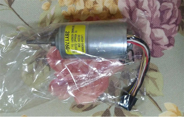
When using an RC ESC to drive the motor, you may notice significant current noise. This is because using back EMF to detect the rotor position isn't as accurate as using Hall sensors. As the motor speed decreases, back EMF becomes weaker, making it harder to detect the rotor position, which can lead to losing sync. Therefore, sensorless brushless motors are more suitable for applications like RC models, which are more rugged and less prone to failure, but their startup and low-speed performance can be quite poor.
For an electric tool, you'll need a sensor-based brushless ESC. The MOSFETs are metal-sealed, but wiring can be complicated, making the setup somewhat challenging. The wiring is numerous, messy, and the color coding isn't very intuitive, so you'll need to figure out the corresponding U, V, and W phases and Hall sensor phase alignment during the wiring process.
Once the bare motor passes initial testing, proceed to identify the wiring scheme. Test the Hall sensor phases HU, HV, and HW, as well as the power supply polarity.
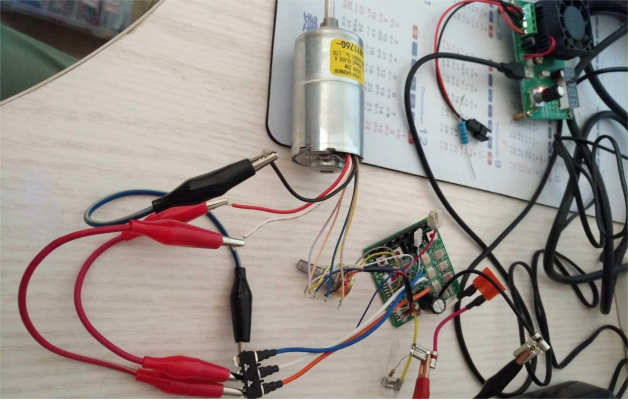
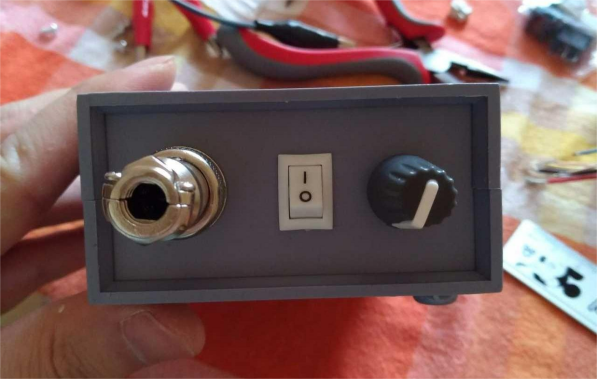
You can modify it to resemble a finished speed controller. Start by placing the board inside a box for measurement. Then, solder an 8-pin aviation connector, drill holes in the front panel to install the potentiometer, forward/reverse control switch, and aviation connector. The board includes battery detection, which might be used for low-voltage protection. Attach a 10kΩ resistor directly to the positive power supply, and connect the forward/reverse control line to a 20kΩ resistor, then to the speed control input. A 20kΩ potentiometer is more suitable, while a 10kΩ one might limit the high-speed performance.
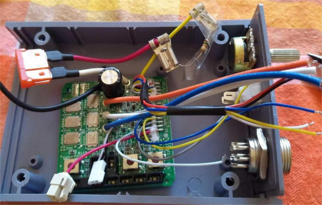
For soldering, use heat shrink tubing for insulation. Any areas not suitable for heat shrink should be insulated with electrical tape. Try to press the wires down to make space for the fan. A 12V 4010 brushless fan works well for cooling. It’s quite powerful, so we added an ST 7805 regulator on both ends of the ESC to help cool the power MOSFETs.
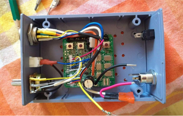
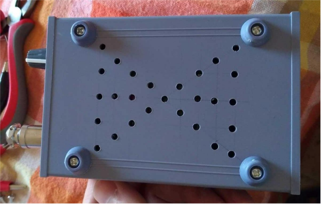
To further enhance cooling, pre-drill ventilation holes for the fan.
This is how it looks with the aviation connectors plugged in.
For the next steps, you can use a pure copper high-power DC socket. Choose a red switch to indicate the power switch, distinguishing it from the forward/reverse switch on the front panel.
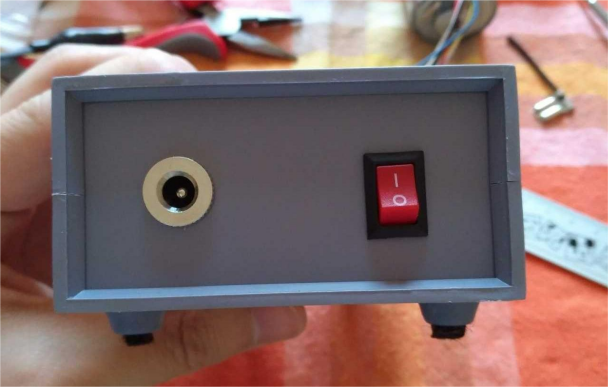
And that's it—completed!


