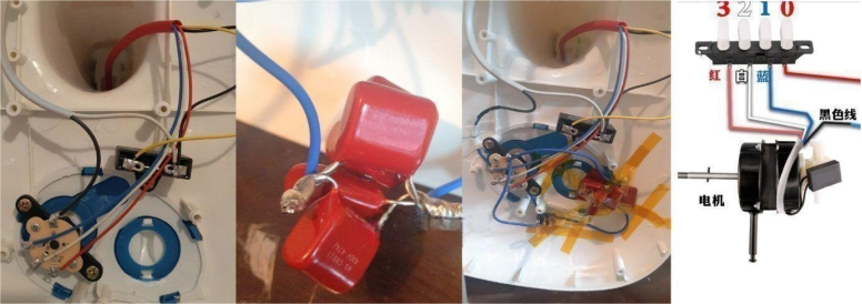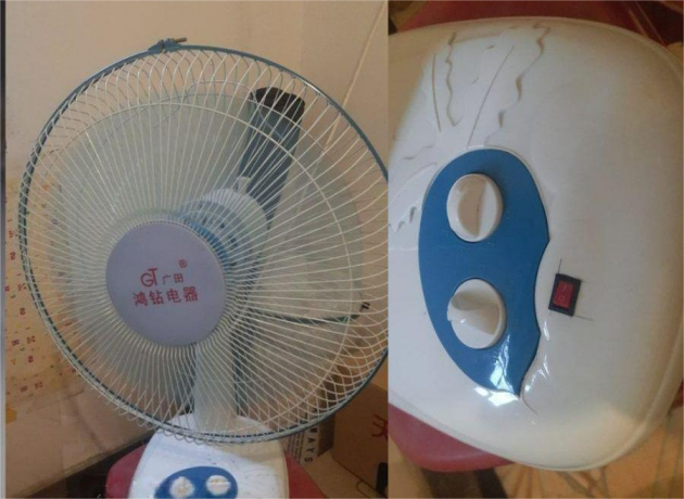
If you're interested in disassembling and modifying a pedestal fan to reduce its speed, take a look at this article.
Based on the power measurements of the pedestal fan, the actual power at different speed settings (1-3) are: 35.55W, 37.1W, and 39.5W, respectively. The airflow nearly doubles with each speed setting, with the power increasing by 4W on setting 3.
Most pedestal fans online use motors with similar configurations, where the third speed is connected directly to different coil windings. The speed settings themselves don’t adjust the power, so the power difference isn’t significant, but the airflow varies greatly. So, what can you do about it?
You can prepare five 630V 0.47uF capacitors and connect them in series to the main power line, along with a switch. (This setup involves five switches and five capacitors.)
The final result: After connecting the five capacitors in parallel and in series on the main line, it equates to 2.35uF.
After the modification, the power for each speed setting (1-3) becomes: 18.1W, 19.4W, and 21.7W, respectively. The maximum airflow on speed 3 is about half of what it was on speed 1 before the modification. The wind is still very strong and can blow through a 15㎡ room, with the airflow decreasing in stages (half the speed of the previous one) from setting 2 to setting 1.
The effect of using three or four capacitors should be the best, providing a gentle breeze with no noise. During the modification process, testing shows that with the added capacitors, the fan starts slower, so you won’t notice the increased airflow until you’ve been using it for a while.
Also, a crucial safety note: Always discharge capacitors before handling them! Be cautious of electric shock. You can use a socket indicator light resistor to short-circuit it, or use a multimeter set to the maximum DC voltage to measure the discharge. Keep checking until the voltage shows a decrease at the decimal point, eventually reaching zero. Simply turning on the fan won’t discharge the capacitor. It's safest to add a 470K resistor in parallel across the capacitor’s terminals before you begin wiring to discharge it!
Capacitive Reactance and Power Calculation:
Capacitive reactance (Xc) = 1 / (2πfC),
where: π = 3.14, f = 50Hz (frequency), C = capacitance (in farads, F).
Current (I) = 220V / Xc
Power (P) = 220V × I
By calculation, the power formula is: Power = 15.2 × C (C in uF)
However, in practice, the result may vary. With five 0.47uF capacitors, the calculated value should be: Power = 15.2 × 5 × 0.47 = 36W, but the actual maximum is only about 60% of the theoretical value, i.e., ~9W (with C in uF).
This discrepancy may be due to different fan models using capacitors of varying capacities for speed reduction. Some fans may only need 1uF, while others may require 2.5uF or even 3uF, and some may require even higher values.
However, there is a general rule: After measuring the power with a power meter, the optimal power reduction occurs when it’s about half of the original value (before using capacitors). If the power goes too low, it could result in high current and low power factor, potentially damaging the fan.
Lastly, fan selection is key: Fans with slow speeds but high airflow are ideal for modification. Fans with high speed but low airflow are not suitable for modification.


