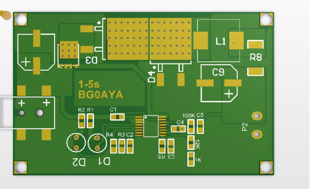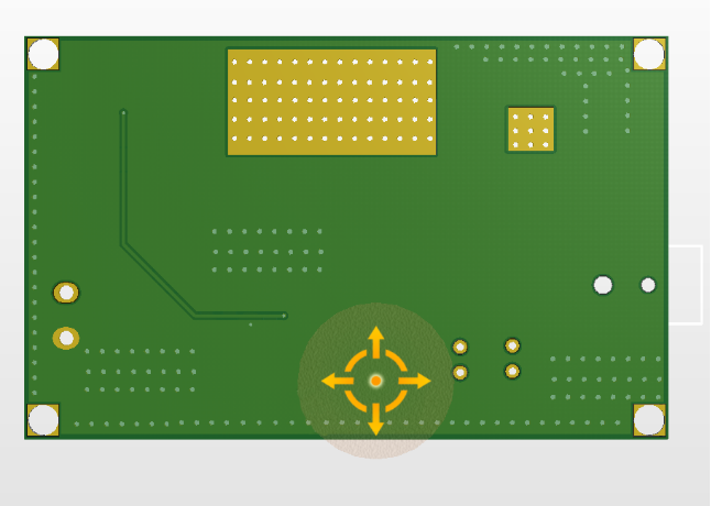
When DIY-ing, you'll come across various battery specifications, and often, you'll need to purchase a new charger. However, cheap chargers typically have average quality and low current output. If you're interested in charging circuit PCBs, this article might be helpful. Follow along as we DIY a 1-5s battery charging module. This module can be used for up to 6s, but it's best suited for 5s. The maximum current it supports is 5A. This module can also be used to charge Makita 21V batteries.
For the chip, you'll need to choose the CN3705. Here are the specifications for the chip:
· Wide input voltage range: 7.5V to 28V
· Full battery charging management
· Charging current up to 5A
· PWM switching frequency: 300kHz
· Constant voltage charging termination voltage can be set with an external resistor
· Constant voltage charging voltage accuracy: ±1%
· Constant current charging current set by an external resistor
· Trickle charge for deeply discharged batteries
· Charging termination current can be set with an external resistor
· Battery temperature monitoring function
· Automatic recharge function
· Charging and charging termination status indicators
· Soft-start function
· Battery overvoltage protection
· Operating temperature range: -40°C to +85°C
· 16-pin TSSOP package
· Lead-free and halogen-free, RoHS compliant


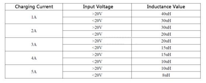
Inductor selection:

Current selection:
1. Resistor Rcs selection:
· For 1A charging current, Rcs = 0.29Ω
· For 2A charging current, Rcs = 0.19Ω
· For 3A charging current, Rcs = 0.067Ω
· For 4A charging current, Rcs = 0.059Ω
· For 5A charging current, Rcs = 0.049Ω
2. Resistor R3 selection:
· When R3 = 0Ω, the charging termination current is 9.17% of the constant current charging current
· When R3 = 100kΩ, the charging termination current is 73% of the constant current charging current. In general, choose R3 as 1kΩ, meaning the charging termination current is 10% of the constant current charging current, which marks the end of the charging process.
Voltage selection:

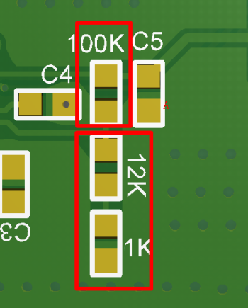
VOUT = 2.416 (1 + upper red box / lower red box). The three resistors here are used for adjusting with a variable resistor. When soldering, simply short-circuit one of the resistors in the lower red box.
Done!


