
If you're interested in LED driver circuits, take a look at this article.
If you've been using LED lights, from the early small power hat-style LEDs, car aluminum heat-sink downlights, to various aluminum PCB chips, and now high-power COBs, you've probably used them all. The more you use them, the more you'll notice that today's LEDs are becoming less reliable—they have shorter lifespans, and it's hard to find lights that last five years without failure. Even with relatively expensive brands, if they last two years, that's considered pretty good. This is primarily an issue of commercial interests, not the LEDs themselves.
In the early days, the main reason for LED failure was damage to the LED chips. Back then, LED technology wasn't as mature, with poor consistency and insufficient heat dissipation structures. This made it easy for individual LED chips to fail due to voltage spikes or poor heat dissipation. Usually, replacing the damaged LED tube would allow continued use. For example, an 8W hat-style LED light could last more than ten years, although its brightness might drop to about a quarter of the original, but this was considered long-lasting.
Now, the main cause of failure in LED lights is overheating, which damages the LED chips or driver components. The quality of LED chips has improved significantly, especially in terms of light efficiency, compared to earlier models.
If you're using them personally, you can modify the driver or the LED board to reduce the power, allowing them to last over two years. However, light degradation will still become severe after a few years. The primary issue now is that the LED boards have poor heat dissipation. The aluminum PCBs are very small, and their design is meant to last only 1–2 years.
So, what should we do?
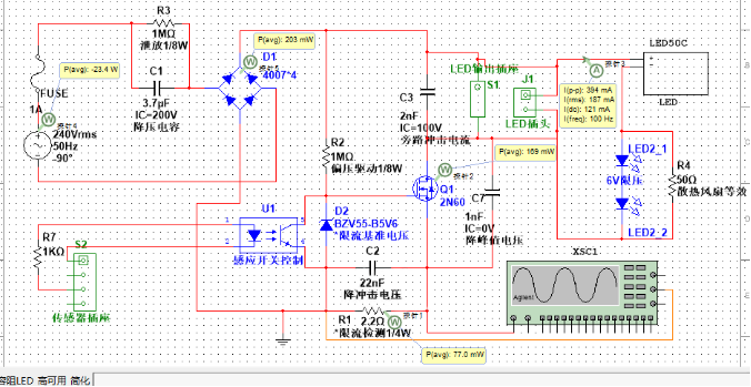
The circuit design is as follows: For long-lasting LED lights, temperature control is key. Proper heat dissipation must be ensured, and the circuit efficiency should be high to reduce heat generation. The design goal is for individual light powers to be between 1-30W, with the LED chip temperature rise around 20 degrees, controlled by an induction module. The basic idea is to limit the current with a high-voltage transistor to prevent voltage spikes from damaging the LEDs when the light is switched on. Afterward, the circuit uses capacitors to limit the current, maintaining high efficiency, although with a low power output.
Below is a circuit for high-power improvements, using high-voltage MOS transistors for current limiting, and adding optocouplers for automatic control. The electrolytic capacitors from the original circuit are removed, which reduces the initial surge current when turned on and extends the lifespan of the step-down capacitors by removing the shortcomings of electrolytic capacitor lifespan.
The circuit efficiency is 98%, which can outperform most commercial LED lights. The downside is that it isn't a constant current circuit, but the difference is barely noticeable. The power factor is around 50%, where the effective power of the step-down capacitors is maximized.
Circuit diagram
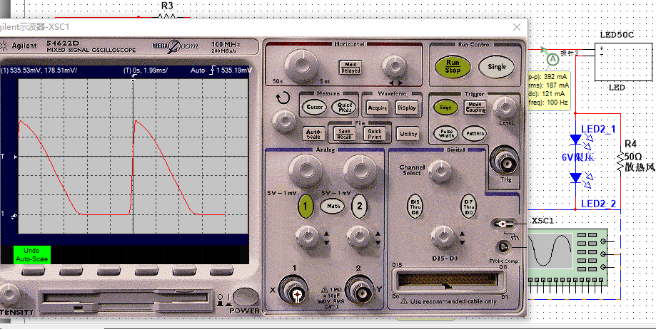
Circuit waveform
DIY suggestions:
1. Do not use low-voltage LED boards; you must use high-voltage boards (at least 60V). It is recommended to use 30 or more diodes, preferably 50 (power factor 50%, maximum effective power). If the power factor is too low, high peak current may burn out the LEDs at higher power.
2. Control power through the size of C1, using multiple CBB or safety capacitors in parallel.
3. Keep the overall power under 50% of the rated power of the LED board to avoid peak current damage and improve light efficiency.
4. When paralleling multiple LED boards, measure their consistency. Poor consistency can lead to LED burnout under high power.
5. For 12W and below, the MOS can be reduced to 1N60, and R1 should be appropriately increased to ensure current limiting accuracy.
6. In the example circuit, the MOS VTO is 3.7V. Actual measurements should be taken, and R1 should be adjusted accordingly. Ensure that the MOS stays in saturation mode after one second of operation, with the temperature rise not exceeding 20 degrees.
7. Use ≥400V CBB or safety capacitors for C1, and ≥600V high-voltage ceramic capacitors for C3 and C7. Use standard 50V ceramic capacitors for C2.
8. The MOS can be as low as 400V, but it's best to add a 400V varistor before the silicon bridge to prevent additional surge voltage caused by poor switch-off performance.
Actual performance: The light board uses a 50C, approximately 50W COB with an active cooling fan similar to a graphics card, drawing a total power of about 20W. The driver circuit is simple, directly built on a perforated board with transparent silicone protection, fixed onto the fan. The fan's drive current is small, and it's only audible when listening closely during quiet nights.
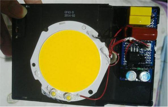
Front view
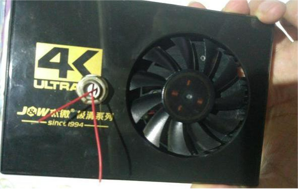
Back view
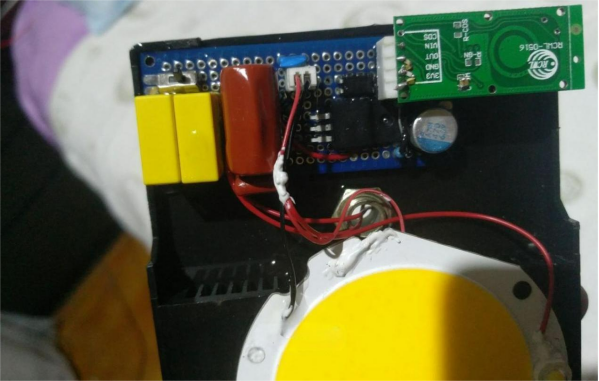
Microwave sensor added
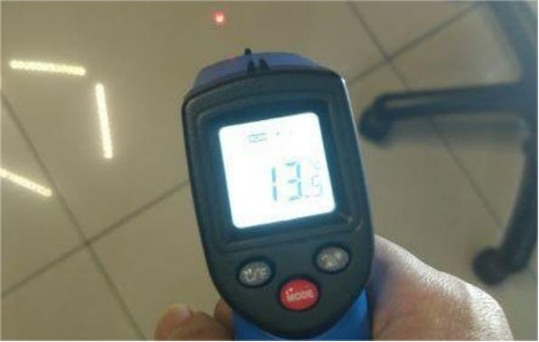
Ambient temperature display as shown
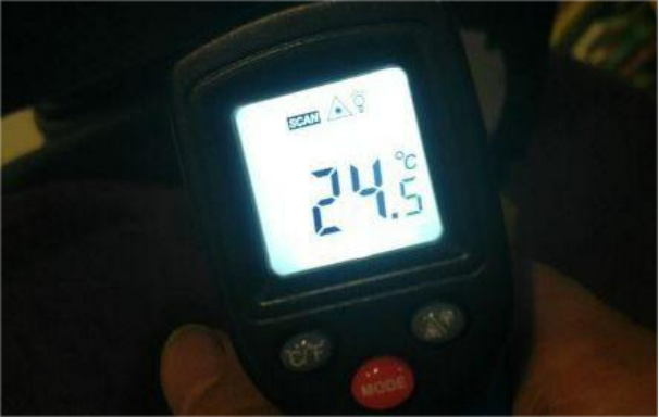
Stable temperature on the aluminum heat sink
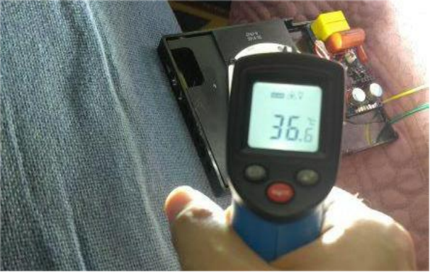
Stable temperature of the LED core, with a temperature rise of about 23 degrees.
After 9 months of use, no light degradation has been detected, and the performance is still great. The end.


