
If you're interested in modifying your Tmall Genie to add AUX output, this article is worth a read.
This guide focuses on modifying the Tmall Genie to output stereo sound. If you're interested, you can try it yourself. Here's a list of the necessary parts and tools you'll need:
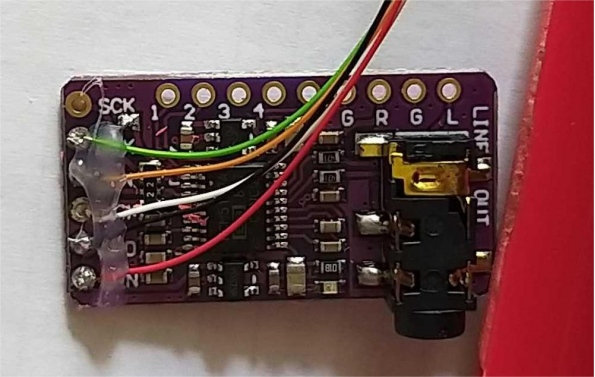
· Decoder board.
· Soldering iron with a fine tip for soldering delicate chip pins and wires.
· Solder paste, which helps with soldering and prevents accidental bridges.
· Hot glue gun to secure solder points and the decoder board.
· Five different colors of fine single-core wires, matching the thickness of the chip pins to ensure good soldering quality.
· Reading glasses, so you can see clearly when soldering.
· High magnification magnifying glass to check the reliability of the chip pin soldering and to spot any cold or bridged joints.
· Electric drill for creating holes for the AUX output.
· 3.5mm audio cable to connect the Tmall Genie AUX output to the amplifier's input.
Steps for Modification:
Start by disassembling the device:
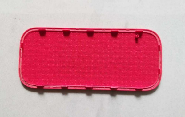
· Use a blade to gently score around the seam between the panel and the casing. Don’t cut too deep—about 1mm. Then, slowly pry the panel off starting from one corner and work your way around the seam. The panel should come off easily.
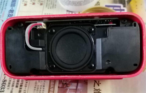
· Once the panel is removed, you'll see the speaker and sound chamber.
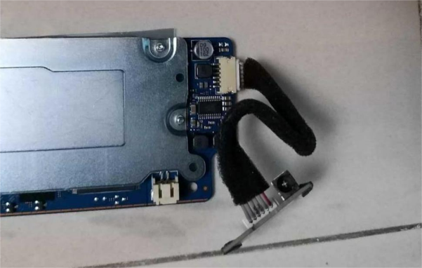
· Use a screwdriver to remove the screws securing the sound chamber, then unplug the ribbon cable from the chamber to detach it. You’ll now see the mainboard and power board.
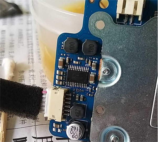
· Remove the screws holding the power board in place, then remove the power board.
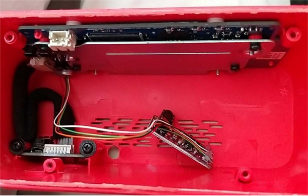
· After unscrewing the mainboard, gently lift the mainboard off the casing, being careful not to tear the rubber pad. Cover the rubber pad with plastic to prevent it from picking up debris.
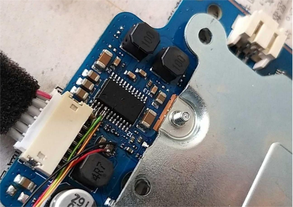
· With the mainboard removed, you'll see the chip and its pins.
Now, follow the wiring diagram provided by the decoder board seller to solder the necessary connections. This is a challenging task that requires significant effort and attention to detail. Sometimes, after soldering the third pin, the connection can break when you solder the fourth pin. Be careful to avoid bridging pins four and five.
Soldering Tips:
Pre-tin the ends of wires and pins to make soldering easier.
· If a bridge occurs, clear it carefully. The solder paste is very useful for both adding solder and clearing any accidental connections.
· After soldering, use a high magnification magnifying glass to check your work.
Next, connect the wires and power up the system for a test. If you hear any noise, you'll need to bridge two points on the decoder board near the bottom right of the SCK to eliminate the noise. Once the connections are confirmed to be good, use the hot glue gun to secure the solder joints.
Drill holes in the appropriate spots to allow the AUX signal output from the decoder board.
Secure the decoder board with glue, then reassemble the parts and put everything back together.
Finally, test the stereo sound by using the Tmall Genie app on your phone to play a track with stereo effects. You should hear the stereo output.
After testing, it turns out the speakers didn't produce true stereo sound. Both speakers played at the same time, and you couldn't hear the effect of a sound moving from left to right, like a train passing. There's a bit of a shortcoming in the final result.
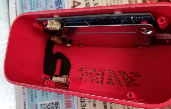
Below are the internal details and external structure of the device:
The End.


