
If you're interested in a DIY adjustable current multi-purpose charger, take a look at this article.
If you have a few broken 936 soldering stations, you can try converting them into T12 soldering stations, or you can follow this article to modify a multi-purpose charger. The charging current is adjustable from 0-3A (limited by the power frequency transformer) and includes over-voltage, reverse polarity, and short-circuit protection.
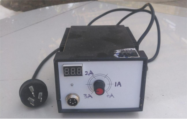
Here is an image of the finished product:
The internal bare device looks like this:
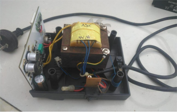
Here's a closer look at the internal bare device, featuring a small heat dissipation fan for the transformer.
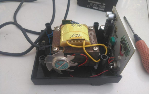
The charger circuit board looks like this:
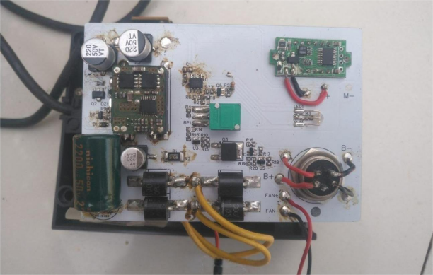
Here's an image of the blank PCB:
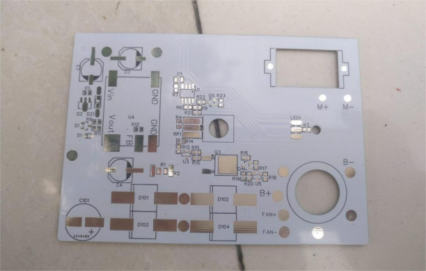
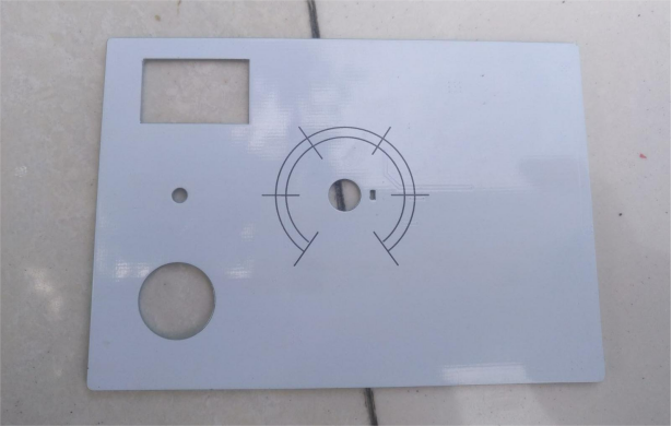
The charging state looks like this, with three series of lithium batteries being charged:
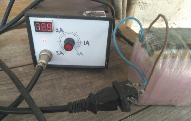
This is how it looks when charging four series of lithium iron phosphate batteries:
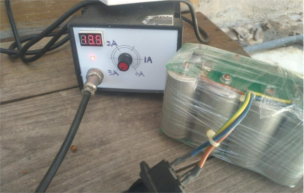
Here's the situation when charging a 12V lead-acid battery (note: no lead-acid battery is connected):
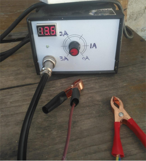
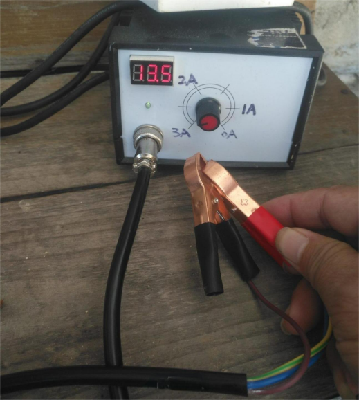
Short-circuit output:
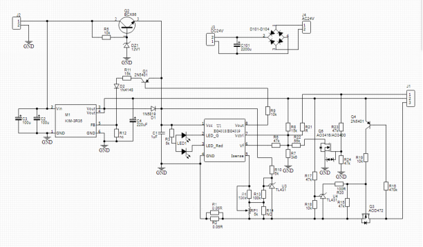
The schematic diagram is shown below. You'll need to adjust the resistor values of R7, R8, and R22 to set the charging voltage anywhere between 2V to 24V for two different sets, or use it as a dedicated three-stage charger for lead-acid batteries. You can decide how many series of battery packs you want to charge.
You'll also need to add an over-voltage protection circuit to prevent the DCDC module from being damaged by direct high voltage output. Adjust the voltage divider ratio of R17 and R18 to set the over-voltage protection voltage.
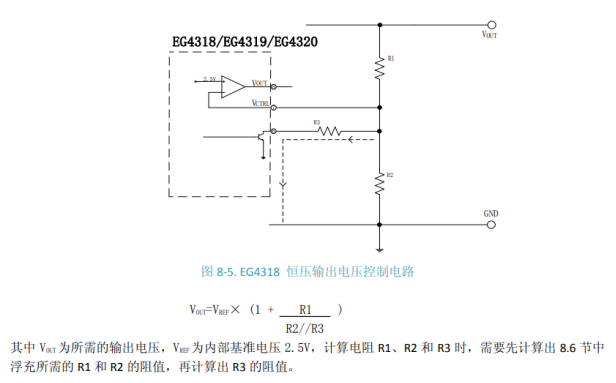
The internal block diagram of the EG4318 is shown below:
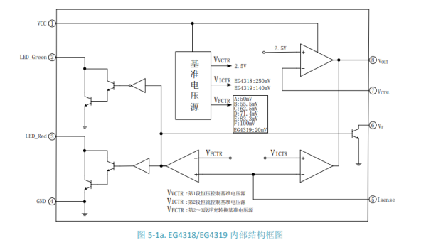
Here's a simple calculation for the charging cutoff voltage of the EG4318. You can refer to the datasheet for more specific applications.
This charger can be used to charge battery packs for small water pumps. The goal is simplicity, reliability, ease of use, and durability. Once the battery pack is drained, you can simply recharge it.
Completed!


