
If you're interested in building a DIY CNC constant current power supply, this article is worth a look.
The centerpiece of this project is a remotely controlled flow valve. All components communicate using RS-485. The valve controls total flow based on a constant current drive, with a maximum output current of 600mA. The valve opening angle is adjusted proportionally to the output current.
If you're short on time, you can skip making a custom PCB and build it directly on a breadboard. Of course, designing a proper PCB is also an option if you prefer a cleaner setup.
For the enclosure, you can use aluminum profiles — they offer slightly better EMI resistance. In the photo, there's a DB9 connector at the front that wouldn't fit due to tall components, so you'll need to remove it. On the right side of the image, near the coil, is an MC34063 chip that generates a negative voltage for the op-amp.
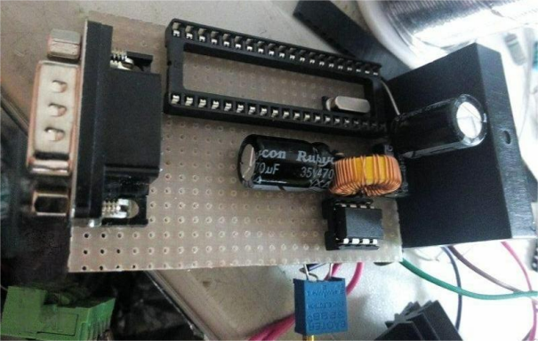
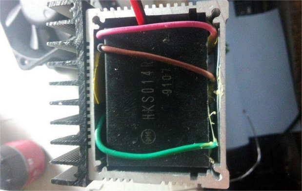
The black module is a power supply that takes up to 42V input and outputs both 5V and 12V.
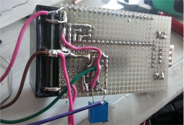
During the testing phase, I swapped out a few different sampling resistors. If your accuracy requirements aren't too high, a standard resistor works just fine for current sensing.
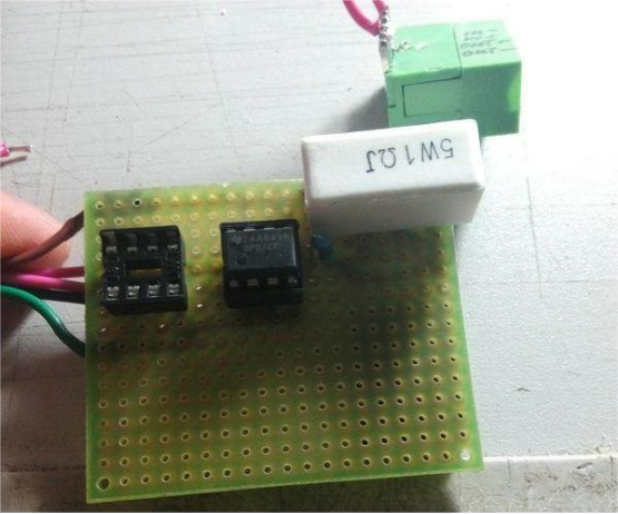
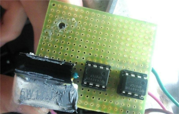
The driver board is on a separate PCB and uses two OP07 op-amps.
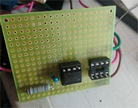
If you're planning to test performance parameters, you'll want to temporarily add a heatsink for the output MOSFET.
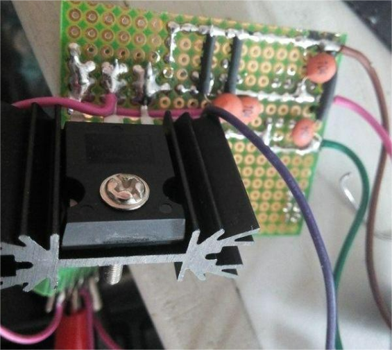
Here's how the MOSFET is ultimately soldered — its heatsink is directly attached to the metal enclosure for better thermal dissipation.
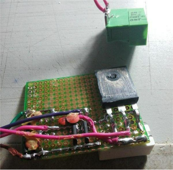
The final current sampling resistor is a 1-ohm cement resistor.
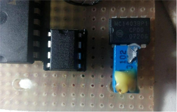
For the microcontroller, you can use an STC 60S2. The DAC is a TLC5615, and the voltage reference is an MC1403. The ADC is handled by the MCU's built-in capabilities. The reference voltage is set to 2.5V, then divided down to 1.024V using a potentiometer.
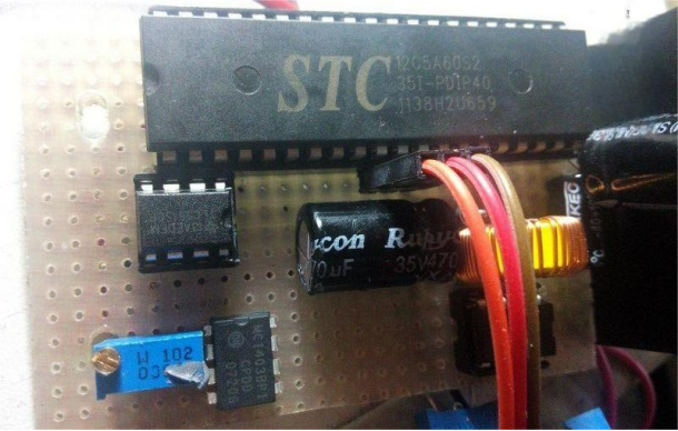
Once you've dialed in the reference voltage, seal the potentiometer with glue to keep it stable.
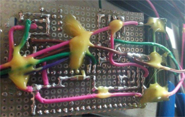
If the wiring on the back of your board gets messy, you can use jumper wires and secure them with yellow glue.
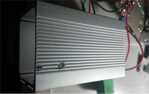
The image below shows the enclosure, with holes drilled to mount the MOSFET.
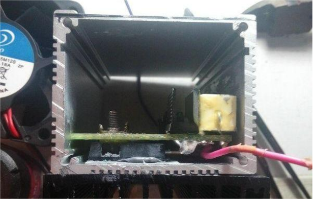
Here's what it looks like after installing the driver board. The MOSFET is pressed against the enclosure, and a heatsink is mounted on the outside.
You'll also need to fit the control board inside the enclosure.
The green terminals are for input, output, and control interfaces.
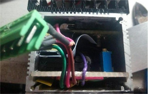
If you have enough space inside your enclosure, you can use DB9 connectors. If not, consider switching to the terminal block style shown below.
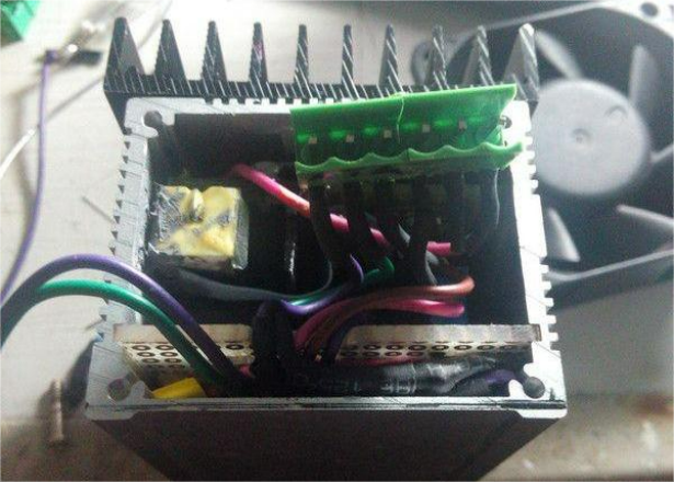
The open end of the case will need to be sealed, and you'll also need to route power lines for a cooling fan.
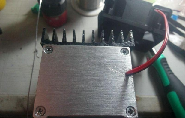
On the other side, you'll need to cut out holes for connectors. If you don’t have access to a CNC machine, you can draw the cutout layout, drill a row of holes along the edge, and finish it off with a file.
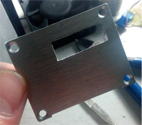
Use AB epoxy glue to fix the connectors in place.
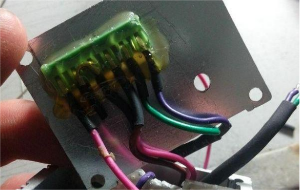
Once everything is enclosed, screw on the lid. You'll also want to attach a heatsink to the aluminum case and install a fan to handle continuous operation.
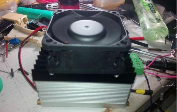
After assembly, it's time to test.
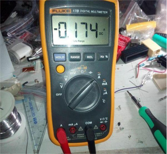
The system uses RS-485 for communication and data testing. The output current is split into 100 steps, from 0 to 600mA. The communication protocol is simple: the first byte is the device ID, the second byte controls the output (00 for off, 01 for on), and the third byte sets the output level. For example, a value of 1D in hex (29 in decimal) corresponds to 174mA.
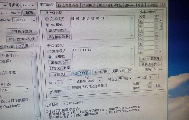
While output current accuracy isn't super high, it's within an acceptable range for most applications.
And that's it — project complete.


