
If you're interested in building your own DIY digital ESC tester, this article might be worth a look.
Let's start by taking a look at the finished product, as shown in the image below.
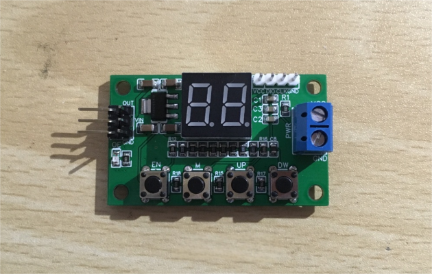
Now, here are a few important things to keep in mind during the building process.
First off, the function of this tester is actually quite simple—it's just meant to control an ESC or test a servo. So, it's not a particularly complex device. Even so, a digital display is definitely the best choice for output, and it's preferable to use a direct-drive 7-segment display instead of a specialized LED driver. Since the speed value only needs to range from 0 to 99, ultra-precise control isn't necessary, so a 2-digit 7-segment display will do just fine.
Next up is choosing the MCU. If price isn't a concern, you could go with an STC 8051 microcontroller. But if you're more cost-conscious, the STM32 F0 series is a better fit—specifically the STM32F030F4P6. It's affordable and offers a great set of features: 16KB of Flash, 4KB of SRAM, a max clock speed of 48MHz, 12-bit ADC, and five timers. Compared to a typical 8051, this is a luxurious upgrade. With such rich features, coding becomes much easier—you won't need to cut corners or squeeze everything in.
That said, there's a small challenge. The STM32F030F4P6 comes in a 20-pin package, with 15 GPIOs available. However, two of these—PA13 and PA14—are used for SWD debugging and programming. While they can technically be reused, it adds complexity. So realistically, you're left with 13 usable GPIOs.
These 13 GPIOs need to handle the following tasks: 4 buttons, one signal output, one output status LED, and the display.
Since the display is 2-digit, it needs 10 GPIOs (8 for segments, 2 for digit selection). If you skip the decimal point, you can get by with 9, but I wanted to implement multiple throttle modes and use the decimal point as an indicator—so cutting corners wasn't an option. That leaves just 3 GPIOs. One is definitely needed for signal output, leaving only two more for the status LED and button inputs. Once the LED takes one, you're down to a single GPIO for reading all 4 buttons.
So how do you read 4 buttons using just one GPIO? This is where ADC key scanning comes in. Essentially, each button is connected through a resistor network that forms a voltage divider. The voltage is read through the MCU's ADC pin, and the resulting voltage level tells you which button was pressed. The main advantage of this method is that it saves GPIOs. The downside is potential signal interference between buttons, more CPU time spent scanning, and the inability to use interrupts. However, for this simple application, those drawbacks are hardly a concern.
Once the plan is set, you can go ahead and design the circuit. The final design uses every available pin on the MCU efficiently—nothing is wasted.
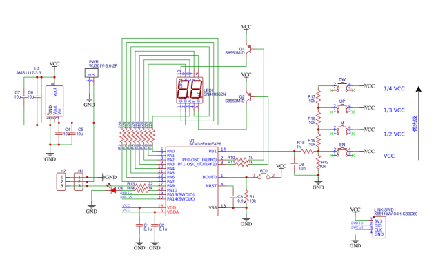
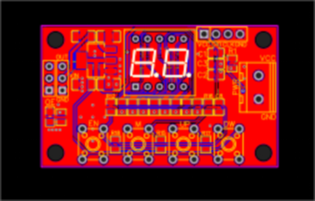
Then comes the PCB design. Since this is a low-speed circuit, routing is straightforward and doesn't require much precision.
Here's a 3D preview of the board.
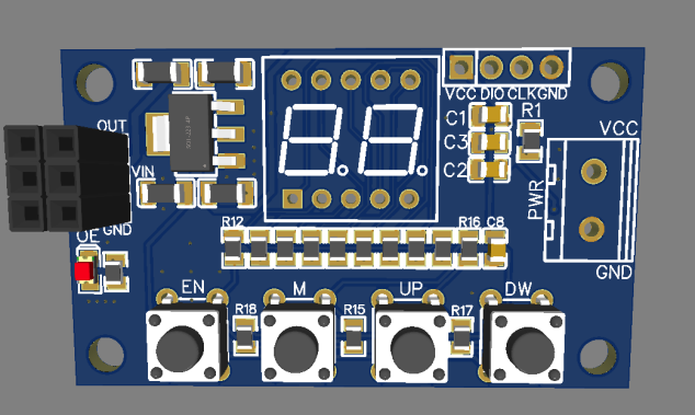
After the PCB design is complete, you can send it out for manufacturing. While waiting, start writing the code. This part is simple: using the STM32's TIM1 advanced timer, you can easily generate a standard PWM signal with a frequency of 50Hz and a high-level duration between 1–2ms.
Once the boards are prepared, solder the components, test the circuit, fix a few minor bugs, and connect it to the ESC. Power it on—and it works perfectly!
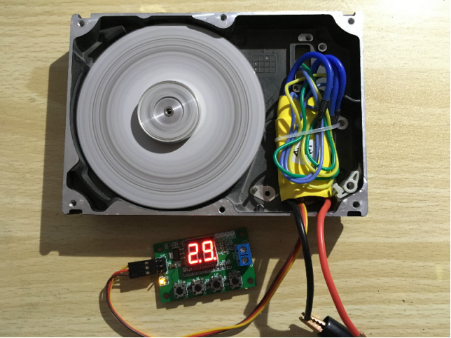
Done!


