
If you're into DIY 12V charging boards, this article might be just what you're looking for.
Most power banks on the market use a 3.7V to 5V boost converter, which is inherently inefficient. Due to the nature of boost DC circuits, it's difficult to achieve high efficiency—hitting even 85% is impressive, let alone 90%. To make the most of stored energy, consider building a buck-type power bank using three 10Ah lithium cells.
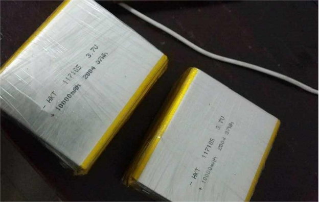
Capacity testing shows each cell discharges from 4.2V to 2.75V with a solid 10.14Ah—genuine performance.
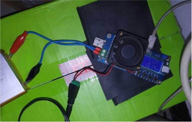
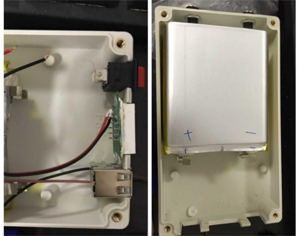
Begin by arranging all the components and lithium batteries in a suitable layout.
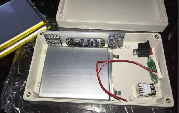
Once the placement looks right, it's time to start assembly. Cut openings for the switch, USB port, and voltmeter.
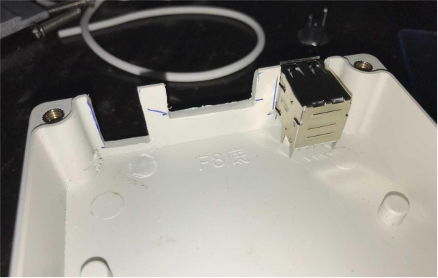
Test-fit everything to ensure proper alignment.
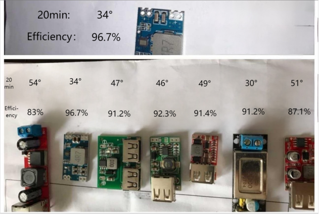
For the USB voltage regulator, several 5V modules were tested. In terms of efficiency and heat management at a 1A load, the mini560 module performed best and is a solid choice.
Mount the module along with a 10A protection board and a balancing board onto an aluminum sheet for better heat dissipation. The protection board handles up to 10A, which is more than enough—especially since these cells have a max discharge rate of 0.5C. The protection board prevents output short circuits, but since it lacks a built-in balancing function, a separate 60mA balancing board is needed.
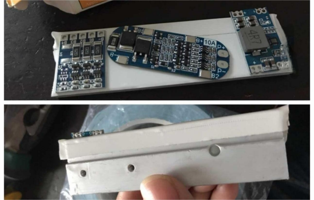
If the 60mA balancing current feels too low, add two more boards in parallel—bringing the current up to 180mA.
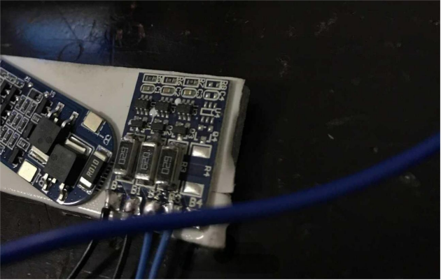
Actual testing shows the balancing current reaches over 200mA, which is sufficient. The MOSFET on the balancing board is an A2SHB, rated for 3A—plenty for this use.
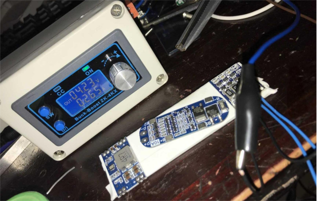
In real-world use, balancing may not even be necessary. The three cells have incredibly consistent voltages—deviation stays under 0.001V. The rear DC jack can be used for both charging and discharging.
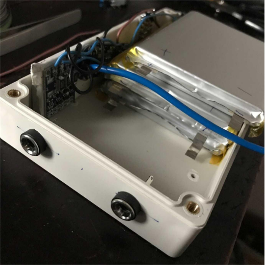
Once everything checks out, install the batteries and solder all connections.
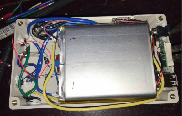
The diode, varistor, and capacitor-fuse combination offers both RC snubbing and reverse polarity protection. The snubber circuit prevents back EMF damage when inductive loads like motors are turned on or off. The diode guards against reversed charger polarity, while the varistor blocks voltages above 16V. Although the protection board already includes reverse and overvoltage protection, adding these safeguards helps keep the board's MOSFETs from being pushed beyond their voltage limits.
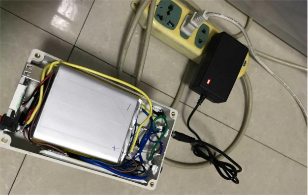
Charging tests show stable performance, with no noticeable heating on the protection board.
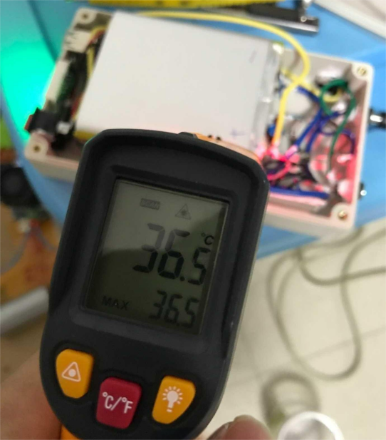
Most 12.6V chargers actually output around 12.75V—often slightly over the rated voltage. This pushes each cell slightly above 4.2V, triggering the balancing board to discharge the excess. The temperature rise is minimal—just a bit above room temperature. One good balance cycle is enough, and it's not necessary to fully charge to 12.6V every time. For ternary lithium batteries, 4.1V per cell already indicates a full charge.
The voltage-to-SOC (State of Charge) reference chart for ternary lithium cells provides a useful guide.
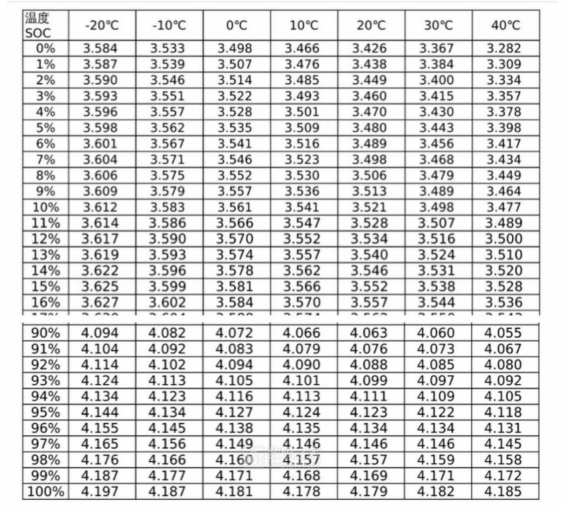
For regular use, 12.3V is a reasonable target. Charging to full capacity brings no real benefit. Once voltage exceeds 4.25V, the electrolyte starts to irreversibly decompose and produce gas, leading to bloating over time. For long-term storage, aim to keep lithium batteries at 50–70% capacity—around 3.6–3.7V per cell.
Project complete.


