
If you're interested in DIYing a 2KV non-inductive component withstand voltage tester, this article is worth checking out.
Traditionally, people use a small HV transformer with an adjustable power supply to test component withstand voltage. But as you work with more electronic components, this setup can become inconvenient. If that’s the case for you, why not DIY your own voltage tester?
1. Work Principle
Circuit Diagram
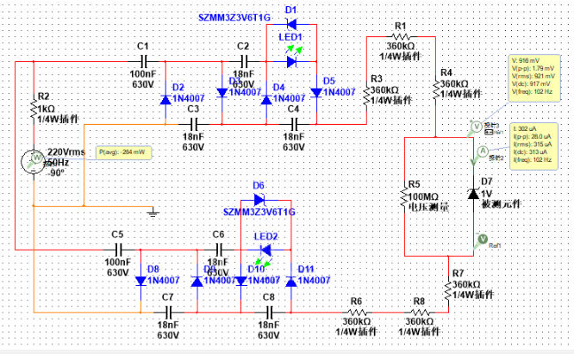
The high-voltage section uses a simple AC voltage-doubling rectifier circuit that works out of the box—no need for tuning, making it great for DIY use.
It features an upper and lower arm configuration, each providing ±1000V. The advantage of this setup is that the measurement point remains near 0V, reducing interference. It also halves the voltage to ground for each arm, which reduces leakage current and power consumption—making it safer overall.
When the two measurement ends are shorted, the LED is at its brightest and the power consumption is highest at about 0.3W (0.3mA), mainly consumed by six current-limiting resistors.
When open-circuited, the LED is at its dimmest, consuming around 50mW with an open-circuit voltage of about 2200V.
The measurement section uses a ready-made 20V 5135 panel meter with a large, clear display (available on Taobao for about ¥14). It has an internal resistance of 1.1MΩ, but other small meters can be used too.
A 1:100 voltage divider network made of ten 10MΩ resistors steps the voltage down. By removing the decimal point jumper on the DP, it becomes a 100MΩ, 2000V-capable panel meter.
2. Construction and Assembly
Virtual Circuit Board
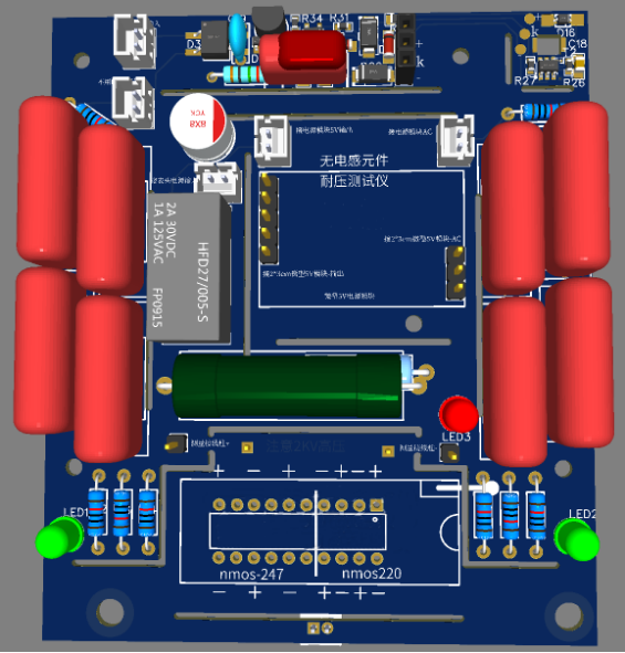
The meter's power supply must be a well-isolated 5V source with low ripple—otherwise, interference will cause the meter to drift.
The enclosure is an 11.5×9cm waterproof box (just a few RMB on Taobao, nearly free with coupons).
Total power consumption is under 1W.
Internal Assembly Diagram
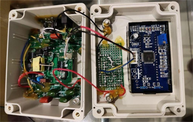
The 1:100 resistor network and test socket are soldered onto a protoboard. A simplified build just needs to cut out the meter section after soldering and mount it to the box lid.
Seal the 1:100 resistor network with silicone to avoid environmental interference.
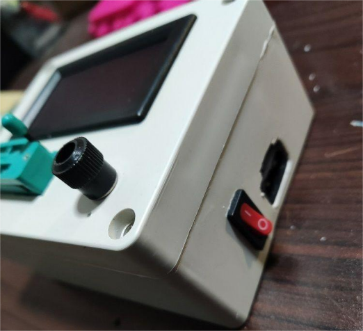
Install the power socket and switch on the side.
Add four dabs of silicone to the bottom of the box and let it dry for anti-slip functionality.
3. Real-World Testing
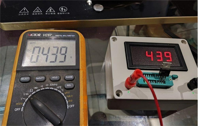
Before use, calibrate the meter using the adjustable resistor. Do not use voltage over 1000V unless your meter supports it—most don't.
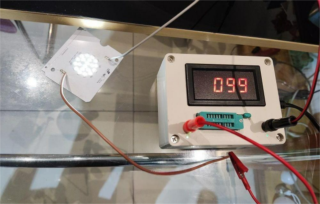
· Testing High Voltage LED
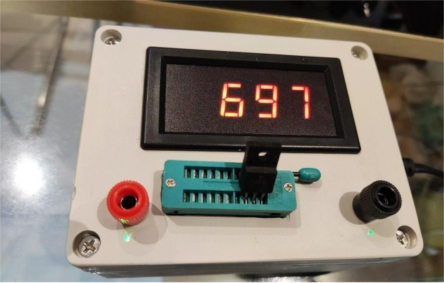
· Testing 650V-rated NMOS
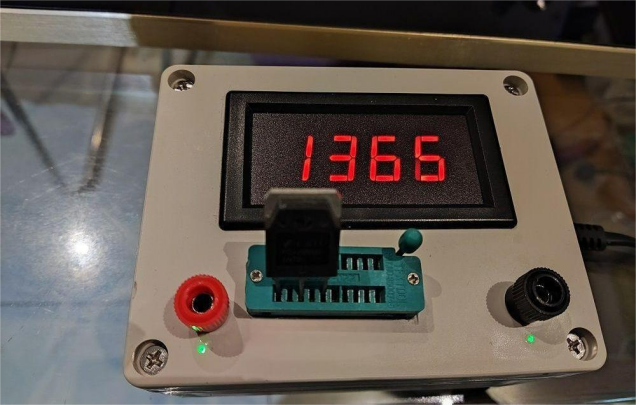
· Testing 1200V IGBT
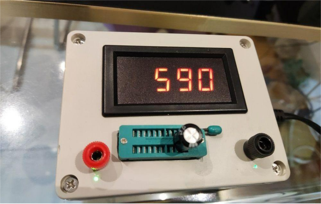
· Testing 450V Electrolytic Capacitor
4. Safety Notes
This tester deals with high voltage. Use it with caution—never operate it while powered on.
1. The Only Safe Operating Procedure
Turn off the device and insert the component
Power on to test
Power off
For capacitors, wait for the charge to dissipate
Then remove the component
2. Personal Safety
The circuit operates at up to 2000V, but with 2MΩ current-limiting resistors and only 5nF capacitance, it won't be lethal. However, shock and tingling are still very likely—do not touch the test terminals directly.
A 2000V potential can create ~1mm arc gaps. Be cautious when using banana plugs—avoid contact with exposed metal.
3. Safety When Charging High Voltage Capacitors
Capacitors store energy. Testing their withstand voltage can leave them charged to high levels—even 100V can be dangerous. Always discharge them safely.
Use high-power resistors for discharging. Never short them directly, which damages both the capacitor's life and capacity.
4. Component Safety Warnings
Verified unsafe components to test:
4.1 Capacitors
With the exception of aluminum electrolytic and 2200V-rated DC capacitors, most other types will be damaged.
Symptoms: internal short, leakage, or reduced capacitance.
Solid-state and polyester capacitors may short.
Common ceramic caps may leak, and MLCC/CBB may lose capacitance.
Aluminum electrolytics are fine—they have higher leakage tolerance and can self-heal via electrolysis.
Capacitors rated 2200V+ like HV ceramic or 630V+ CBB types can handle the test but shouldn’t be shorted afterward, or they’ll degrade too.
4.2 High-Value Resistors (>4MΩ)
(e.g., 1/4W through-hole and all SMDs)
They may lose resistance accuracy or stability, especially when used in voltage dividers for 1000V+—a regular multimeter might even damage them.
4.3 MOSFET Gate Voltage (Vgs)
Exceeding Vgs will short the MOSFET.
When testing MOSFET forward voltage, always short the gate to source.
Never test with gate open—it causes Vgs to rise due to distributed resistance.
Here PCB includes a special NMOS socket for TO220 and TO247.
Some parts must only be tested when powered off. Powering on with the component already connected avoids dangerous arcs and voltage spikes.
4.4 LED Reverse Voltage
Reverse testing creates arcs and kills LEDs—either shorted or open.
4.5 Schottky Diode Reverse Voltage
A few tests with arcs can cause short failures.
4.6 1000V Diodes like 1N4007
During reverse-limiting tests (e.g., using M7), some units fail over time—likely due to sustained high power.
Other components like BJTs, Zener diodes, and varistors are more stable—haven’t had failures even under arc discharge. But sample size is small. As long as you follow safe procedures, you're fine.
5. Optional Enhancements for This Version:
1. Add Auto-Discharge After Capacitor Testing
· When testing capacitors, auto-discharge when power is off
· Add a red LED that lights during discharge and turns off when safe
· Use relays like NEC EC2, Panasonic TX2, Hongfa HFD2 (5V versions)
· Test relay breakdown voltage first; use two relays in series if one is under 2000V
· Discharge resistors: three 2W, two 3W, or one 7W work well
· Tested safely under 2KV/0.3uF and 500V/100uF loads
· Remove the output capacitor on the power module—this ensures instant shutdown of the relay
· The meter can still show voltage for a few seconds thanks to capacitor C17
2. Add a Touch Switch Instead of a Mechanical One
· Use a compact 1cm x 1cm touch switch
· Solder leads, fix it inside the top panel with hot glue
· Pre-drill a small hole in the case for the LED, seal with silicone
· LED shows power status, switch is touch-based—more user-friendly
· This module can also control small lamps (under 30W with SOT23 TRIAC or 40W with TO92), but you'll need to test and verify yourself.
End


