
If you're interested in building your own DIY 6S balanced charger, this guide is worth a look.
The B6 charger is a pseudo-balanced design, and many RC model chargers suffer from both poor balancing accuracy and excessive current, which often leads to imbalance issues. So how can you build a truly balanced charger from scratch? Let's dive in.
To start, you'll need seven 5V 2A power modules. These compact power boards come with two tantalum capacitors onboard and are highly space-efficient.
You'll also need a set of TC4056A charging boards, two cooling fans, and aluminum heatsinks for thermal management.
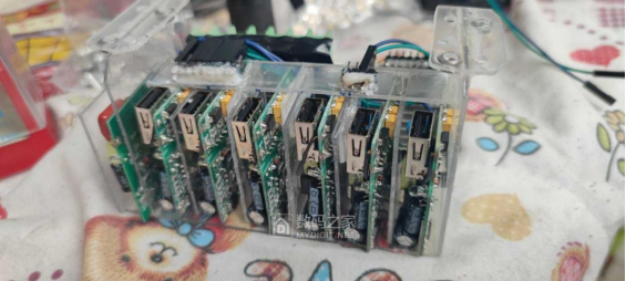
For structure, you can use an acrylic power supply bracket to isolate each module. This design not only allows easier maintenance and replacement when one unit fails but also shows off the tantalum capacitors clearly. Each power module includes a blue LED for visual status, and one of the modules without capacitors can be dedicated to powering the cooling fans.
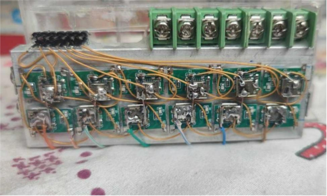
For thermal dissipation, mount the TC4056A boards onto a single large aluminum heatsink. Use PTFE silver-plated wires for secure and efficient connectivity.

When assembling the power modules, DuPont wires can simplify connections and allow quick module replacement if needed.
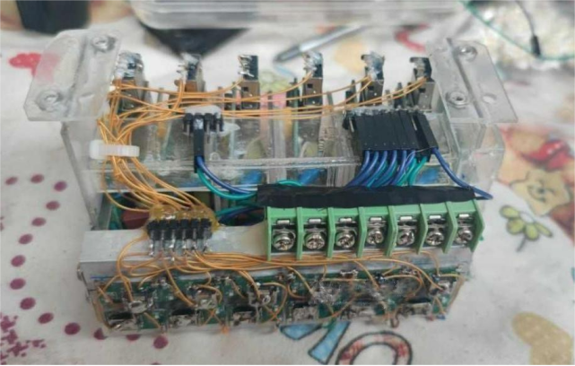
Use terminal blocks for wiring the TC4056A boards to enhance durability and make maintenance easier by avoiding wire bending during assembly.
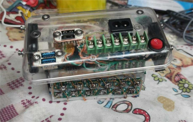
The top cover and the acrylic internal frame are designed as a detachable unit, allowing easy extraction for repair.
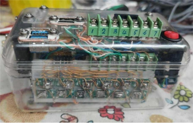
During assembly, the cover and case are held together with eight screws positioned around the dual cooling fans. Removing four fan screws allows the top cover and internal structure to slide out effortlessly.
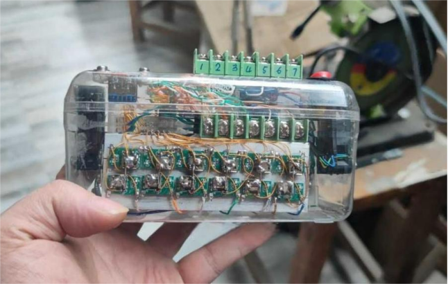
The output terminals are mounted on the top panel, providing seven posts for direct battery connections. This setup allows you to conveniently measure the voltage of each battery group using a multimeter. USB 3.0's 9-pin design can power 6S batteries using seven of its pins, and standard USB charging cables are compatible.
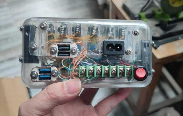
Consider adding two extra USB ports so the system remains functional even if one port fails.
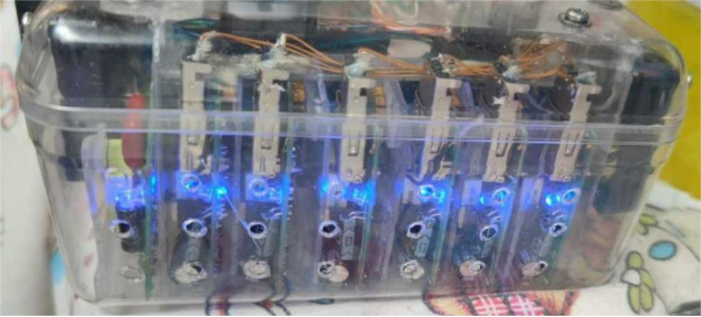
Each of the six channels uses two TC4056A chips (2A per chip), offering a total charging power of 48W. In practice, the input reaches about 65W from the wall socket.
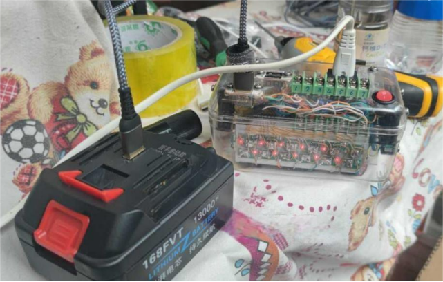
To complement the balanced charger, you can also create a dedicated testing dock. After modifying a battery for USB use, you can first test the pin configuration using the dock to prevent incorrect wiring, which could otherwise damage the TC4056A during charging.

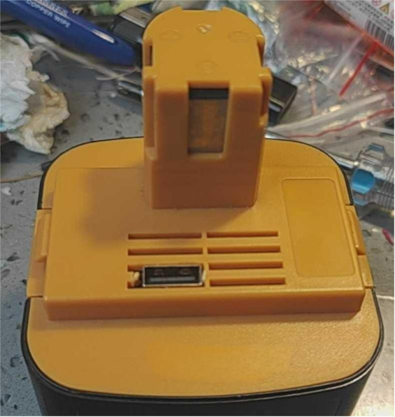
Using USB connectors makes assembly simpler and more compact. A 12V battery can use a USB 2.0 female port, while anything above 12V should use USB 3.0. You can standardize the wiring by using USB 3.0 cables across all configurations. With a 2A current rating, USB cables can handle the load reliably. This current range (2A) is also well-suited to most batteries, which typically range from 1300mAh to 4000mAh—ensuring a reasonable charge time and prolonged battery life.
As for concerns about TC4056A's voltage accuracy, it performs quite well—usually between 4.195V and 4.206V—which is safer than many RC chargers that tend to overcharge. Pseudo-balanced chargers also struggle with low balancing current, significantly increasing the time needed for a full charge.
Lastly, if you're wondering why the 5V input wires are so thin: in theory, a Schottky diode should be used in series with the TC4056A to drop about 0.3V, reducing heat generation. Since these boards lack Schottky diodes, thinner wires help reduce voltage slightly, acting as a rudimentary heat management strategy. While this introduces minor line loss, it's less than 0.3V and contributes positively to thermal control—making thin wires preferable in this case.
Project complete.


