If you're interested in a DIY M8-based microcontroller constant current digital electronic load and AC internal resistance tester, this article is worth checking out.
Core Features
· Constant current electronic load
· Battery capacity testing
· Maximum working current test for switching power supplies
· AC internal resistance measurement
Specifications
· A/D Conversion: 10-bit ±1 (using 64x oversampling)
· Voltage Display: Up to 50V, ±50mV (with 64x oversampling, reduced to ±10mV accuracy)
· Current Display:
- Up to 5A: ±5mA (using 0.05Ω sampling resistor, current = 0.25V / 0.05Ω)
- Up to 30A: ±30mA (using 0.0083Ω sampling resistor)
· Current Adjustment:
- 13-bit PWM D/A
- Minimum resolution: 1mA (5A range), 4mA (30A range)
· AC Internal Resistance Measurement Range: 0 – 500mΩ (measured at 10mA, 1kHz)
- Adjustable using R7:
- R7 = 50Ω → 0 – 500mΩ
- R7 = 100Ω → 0 – 1000mΩ
Circuit Configuration
· PC4 (ADC4) of the M8 is used for alarm output (100Hz signal)
· Remove R60, and use PB2 (OC1B) as the 1kHz AC source output for internal resistance testing
· Remove R25, and use PC3 (ADC3) as the input for AC resistance ADC measurement
· PC2 (ADC2) serves as the voltage input for the low-voltage range (0 – 4.5V)
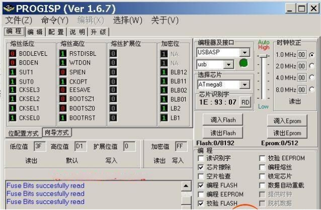
M8 Fuse Bit Settings

Additional Functional Enhancements
· Current Display Zero Calibration: To reduce offset errors caused by amplifier temperature drift
· Startup Current Display Zeroing: For better accuracy at power-on
· Serial Output Format (once per second, values without decimal points):
- Current (mA), Voltage (mV), Capacity (mAh), DC Resistance (mΩ), AC Resistance (0.1mΩ)
· Added ADC2 Voltage Input:
- Can use two 100K resistors for voltage divider
- Enables accurate measurement of voltages below 5V
- Includes V1 (ADC2) calibration
1. Modified Serial Output Format

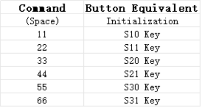
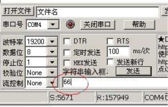
2. Added Serial Port Virtual Button Controls


Finished.


